Performance verification Test
EN
Copyright © Qingdao Hantek Electronics Co., LTD DPO7000 Performance Verification Guide
13
4.3.1 Index
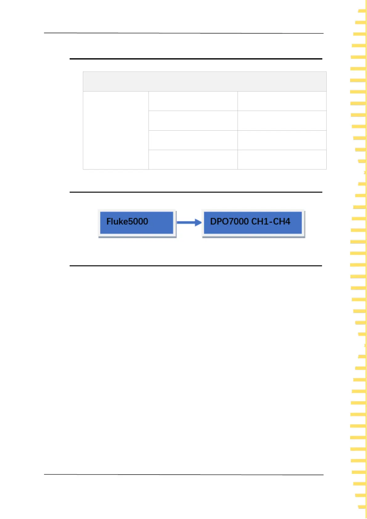
4.3.2 Test Connection Diagram
4.3.3 Test Procedure
1. Connect the active signal probe of Fluke5000 to the CH1 channel of the
oscilloscope and follow the test connection diagram.
2. Open Fluke5000 and set its impedance to 1 M Ω.
3. Configure oscilloscope:
⚫ Click [CH1] in the button area to open the CH1 menu.
⚫ Click on the Attenuation menu and set the probe attenuation ratio to 1X, with
a default value of 1X.
⚫ Add a 50 ohm adapter at the CH1 channel connection.
⚫ Set the horizontal time base to 500 ns/div.
⚫ Set the vertical gear to 100 mV/div.
⚫ Set both horizontal and vertical offsets to 0.
⚫ Set the trigger level to 0 V.
4. Output a sine signal with a frequency of 1 MHz and an amplitude of 600 mVpp (V)
through Fluke5000.
5. Click on the [Meas] menu, select the data source as CH1, select the measurement
item as amplitude, read and record V1.
 Loading...