83
1. Configure each function and range in the order shown in the table below.
2. Apply the input signal shown in the Input column.
3. Input the actual input current as the calibration value.
The message Calibration
Step Succeeded indicates success.
If the display shows Calibration Step Failed,
check the input value, range, function, and the input calibration value and repeat the
calibration step.
4. Repeat steps 1 to 3 for each gain calibration point shown in the table.
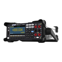
The calibration points of HDM3000 are as follows:
Ohms Gain Calibration
Configuration This procedure adjusts the gain of the 2-wire and 4-wire resistor functions as
well as the offset compensation resistor functions.
1. Configure each function and range in the order shown in the table below.
2. Apply the input signal shown in the Input column.
3. Enter the input resistance for the actual application (see Input calibration values).
The
message Calibration Step Succeeded indicates success.
If the display shows
Calibration Step Failed, check the input value, range, function, and the input
calibration value and repeat the calibration steps.
4. Repeat steps 1 to 3 for each gain calibration point shown in the table.
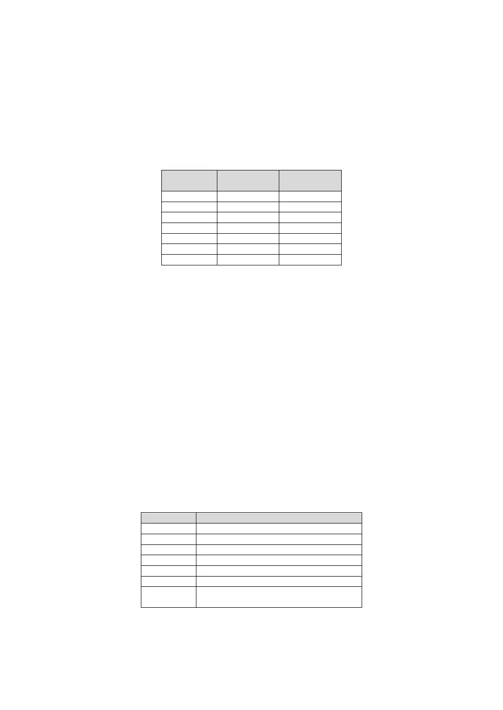
The calibration points of HDM3000 FRES are as follows:
Input HI short circuits Sense HI.
Input LO short circuits Sense LO.
 Loading...