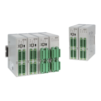
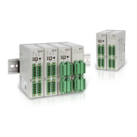
Multi Loop Controller
20
Register range Details
4 0001(0) ~ 4 0099(63) CH1~2 PV, SV, MV, TSV, CHSTS, EVSTS and common channel setting ※ Please use address
40000 for Modbus
communication
4 0101(65) ~ 4 0199(C7) CH1 related setting
4 0201(C9) ~ 4 0299(12B) CH2 related setting
Register address
(HEX)
Symbol
Description
Property
(R/W)
Setting range Unit
Initial
value
CH1 CH2
n : Number
of channel
1(1) 2(2) PV Process value R EU(0 ~ 100%) ℃ -
6(6) 7(7) SV Set value R/W EU (0 ~ 100%) ℃ EU (0%)
11(B) 12(C) MV Manipulated Value R 0.0 ~ 100.0 % -
16(10) 17(11) CHSTS Channel status R
OR run for situation occurrence
15 Bit: Set “1” at System Data error
14 Bit: Set “1” at Calibration Data error
13 Bit: Set “1” at input circuit error
12 Bit: Set “1” at EEPROM error
11 Bit: Set “1” after 24 hours of auto toning (AT)
10 Bit: Set “1” at standard contact point correction
(RCJ) error
9 Bit: Set “1” when exceeding ±5% input range
8 Bit: Set “1” at input sensor error (B. OUT)
2 Bit: Set “1” at auto tuning (AT) running
1 Bit: Set “1” at monitor mode
0 Bit: Set “1” at run start
ABS -
21(15) 22(16) TSV Target set value R EU (0 ~ 100%) ℃ EU (0%)
26(1A) EVT_STS Event status R
Indication of occurrence to all events previously set
0: no event occurred
1: event occurred
ABS -
27(1B)
EVBUS_STS
Event Bus output
status
R
Event bus output OR run
7 Bit(128): Set “1” at event bus8 output occurrence
6 Bit(64): Set “1” at event bus 7 output occurrence
5 Bit(32): Set “1” at event bus 6 output occurrence
4 Bit(16): Set “1” at event bus 5 output occurrence
3 Bit(8): Set “1” at event bus 4 output occurrence
2 Bit(4): Set “1” at event bus 3 output occurrence
1 Bit(2): Set “1” at event bus 2 output occurrence
0 Bit(1): Set “1” at event bus 1 output occurrence
ABS -
31(1F) LOCK
Parameter change
lock
R/W
0: possible to edit all parameters
1: possible to edit only SV, R/S, AT, CHEN
parameters
2. impossible to edit all parameters
ABS 0
32(20)
COMCHK
Time setting for
RS485 communication
disconnection detection
time
R/W
0 : OFF
1 ~ 3,600
sec.
0 (OFF)
33(21)
PARA_SAVE
Setting of communication
used parameter save
R/W
0: Automatic parameter save
1: save manually using PARA_COPY
parameter
ABS 0
34(22)
PARA_COPY
Run parameter save R/W
1: When PARA_SAVE “1” is set, save
parameters manually
ABS 0
36(24) 37(25)
CHMD.n Set channel mode R/W
0:Stop mode
1: Monitor mode
2: Run mode
ABS 0
41(29)
42(2A)
AT.n
Run PID auto tuning (AT)
R/W
0: PID auto tuning (AT) stop
1: PID auto tuning (AT) start
ABS 0
46(2E) R/S Run setting R/W
0: run stop (STOP)
1: run start (RUN)
ABS 0
3.2.2 ML-D2H register description
 Loading...