EasyManua.ls Logo

Harbor Breeze ARMITAGE CC52WW5C1 - User Manual

Harbor Breeze ARMITAGE CC52WW5C1
17 pages
Print Icon
To Next Page IconTo Next Page
Loading...
ITEM #0020776
ARMITAGE CEILING FAN
MODEL #CC52WW5C1
Harbor Breeze® is a registered trademark of
LF, LLC. All Rights Reserved.
Español p. 18
1
ATTACH YOUR RECEIPT HERE
Serial Number
Purchase Date
Lowes.com/harborbreeze
EB15412
Questions, problems, missing parts? Before returning to your retailer, call our customer
service department at 1-800-643-0067, 8 a.m. - 6 p.m., EST, Monday - Thursday, 8 a.m. -
5 p.m., EST, Friday.
4007498
Question and Answer IconNeed help?

Do you have a question about the Harbor Breeze ARMITAGE CC52WW5C1 and is the answer not in the manual?

Summary

SAFETY INFORMATION

DANGER Warnings

Ensure outlet box is securely attached and supports fan weight.

General Safety Warnings

Mount fan to approved box, use correct wiring, avoid dimmer switches, use provided parts, shut off power.

Electrical Safety Precautions

Ensure outlet box is properly grounded. Check all screws, bolts, and nuts for security.

PACKAGE CONTENTS

PREPARATION

Parts Verification

Verify all parts are present and undamaged before assembly.

Assembly Guidance

Estimated assembly time is 120 minutes. Gather required tools.

INITIAL INSTALLATION

Power Shut-off Procedure

Disconnect power at circuit breakers and wall switch before installation.

Mounting Location Requirements

Ensure blades are 7 ft from floor and 30 in from obstructions. Flushmount only.

Mounting Bracket Preparation

Remove nuts and washers from mounting bracket.

Mounting Bracket Installation

Attach mounting bracket to outlet box using provided hardware.

Motor Assembly Preparation

Remove motor screws and lock washers for later use. Discard plastic blocks.

Temporary Motor Hanging

Hang motor assembly on 'J' hook of mounting bracket for wiring support.

WIRING

Wiring Diagram Options

Illustrates connections for pull chains only, pull chain/wall switch, and two wall switches.

Wire Connection Best Practices

Wrap wire connectors with tape. Ensure no bare wire is visible. Place connections neatly.

Dimmer Switch Usage Prohibition

Do not use dimmer switches for fan speed control to avoid humming and shock.

FINAL INSTALLATION

Motor Assembly Securing

Secure motor assembly to mounting bracket using washers and nuts.

Motor Housing Attachment

Align and secure motor housing to mounting bracket with screws and lock washers.

Blade Arm to Blade Connection

Attach blade arms to blades using blade screws and fiber blade washers.

Blade Arm to Motor Connection

Secure blade arms to motor using motor screws and lock washers.

Shade Fitter Plate Installation

Secure shade fitter plate with screws and washers. Thread pull chains.

Bulb and Shade Assembly

Install the light bulb. Allow cooling before touching bulb or shade.

Glass Shade Attachment

Align glass shade slots with plate protrusions. Turn clockwise to secure.

Pull Chain Extension Installation

Attach pull chain extensions to fan and light pull chains as needed.

OPERATING INSTRUCTIONS

Fan Speed Control

Use pull chain to select HIGH, MEDIUM, LOW, or OFF fan speed.

Light Operation

Use pull chain to turn the light ON or OFF.

Fan Direction Adjustment

Use reverse switch for seasonal airflow optimization. Wait for fan to stop.

Seasonal Airflow Modes

DOWN for summer (wind chill), UP for winter (heat circulation).

Reverse Switch Functionality Check

Ensure reverse switch is fully UP or DOWN for fan operation.

CARE AND MAINTENANCE

Routine Maintenance Checks

Check and tighten screws twice yearly. Clean housing and blades with soft cloth.

Bulb Replacement Guidelines

Use 60W max. candelabra bulbs or 13W CFLs. Allow cooling before replacement.

TROUBLESHOOTING

Fan Not Moving Solutions

Check reverse switch, power, and wiring connections for troubleshooting.

Noisy Fan Operation Solutions

Check blade tightness, cracks, dimmer switch, and motor housing security.

Excessive Wobbling Solutions

Tighten blades, re-install blade arms, balance blades, or check mounting security.

Light Failure Diagnosis

Check bulb installation, wiring in outlet box, and wall switch status.

LIMITED LIFETIME WARRANTY

Warranty Coverage and Exclusions

Covers defects. Excludes finish changes, damage from misuse, or unauthorized service.

Warranty Service Process

Present sales receipt. All removal/reinstallation costs are purchaser's responsibility.

REPLACEMENT PARTS LIST

Parts Identification and Numbers

Lists part numbers for Mounting Bracket (A), Blade Arm (F), and Blade (G).

Overview

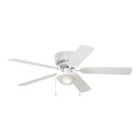
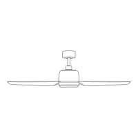
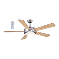
The Harbor Breeze Armitage Ceiling Fan (Model #CC52WW5C1, Item #0020776) is a flushmount ceiling fan designed for indoor use. It features a traditional design with five blades and an integrated light kit. The fan is suitable for rooms where a minimum clearance of 7 feet from the blades to the floor and at least 30 inches from the end of the blades to any obstruction can be maintained.

Function Description:

The Armitage Ceiling Fan provides both air circulation and illumination. The fan speed is controlled by a pull chain, offering four positions: HIGH (one pull), MEDIUM (two pulls), LOW (three pulls), and OFF (four pulls). The light kit is controlled by a separate pull chain, allowing it to be turned ON or OFF independently. For enhanced seasonal performance, the fan includes a reverse switch located on the switch housing. In warmer weather, setting the reverse switch to the DOWN position creates a downward airflow for a wind chill effect. In cooler weather, setting the switch to the UP position generates an upward airflow to help move stagnant, hot air off the ceiling area. It's crucial that the reverse switch is set either completely UP or completely DOWN for the fan to operate; a middle position will prevent the fan from functioning.

Important Technical Specifications:

  • Mounting Type: Flushmount (for regular, no-slope ceilings only).
  • Fan Support: Must be mounted to an outlet box marked "ACCEPTABLE FOR FAN SUPPORT OF 35 LBS. (15.9 KG) OR LESS." A METAL octagonal outlet box secured directly to the building structure is required, capable of supporting at least 35 lbs.
  • Clearance: Minimum 7 ft. from blades to floor, minimum 30 in. from blade ends to obstructions.
  • Electrical Connections: Designed for one 12-gauge house wire and two lead wires from the fan. Consult an electrician if house wire is larger than 12-gauge or if there are more than one house wire to connect.
  • Light Kit: Uses 60-watt max. candelabra-base bulbs or 13-watt candelabra-base CFLs. One bulb (I) is included.
  • Net Weight: 14.11 lbs. (including light kit).
  • Power Supply: 120 V.
  • Controls: Pull chain for fan speed, pull chain for light. Not compatible with solid state speed control devices or full range dimmer switches for fan speed control, as this can cause humming and poses a fire/electrical shock risk.

Usage Features:

  • Easy Installation: The manual provides detailed steps for securing the mounting bracket, assembling the motor housing, and attaching the blades. A "J" hook on the mounting bracket temporarily supports the fan during wiring, simplifying the process.
  • Wiring Options: The manual illustrates three wiring diagrams to accommodate different control preferences:
    • Fan and Light Controlled by Pull Chains: Both fan and light are operated via their respective pull chains.
    • Fan Controlled by Pull Chain, Light by Wall Switch: The fan is controlled by its pull chain, while the light is controlled by a separate wall switch.
    • Fan and Light Controlled by Two Wall Switches: The fan and light are independently controlled by two separate wall switches.
  • Seasonal Performance Optimization: The reverse switch allows users to adjust airflow direction to suit warmer or cooler weather, enhancing comfort and potentially reducing energy consumption by optimizing thermostat settings.
  • Pull Chain Extensions: Two pull chain extensions (H) are supplied, or custom extensions can be used, for convenient access to the fan and light controls.

Maintenance Features:

  • Regular Inspections: At least twice a year, the motor housing (C) should be lowered to check the motor assembly (D) and all fan screws should be tightened.
  • Cleaning: The motor housing (C) should be cleaned with only a soft brush or lint-free cloth to prevent scratching the finish. Blades (G) should be cleaned with a lint-free cloth. A light coat of furniture polish can be applied to wood blades for added protection.
  • Bulb Replacement: When replacing the bulb, allow the bulb (I) and glass shade (E) to cool down completely before touching them. Use 60-watt max. candelabra-base bulbs or 13-watt candelabra-base CFLs.
  • Safety Precautions: Always shut off the main power supply at the circuit breaker or wall switch before performing any maintenance or installation to avoid electrical shock. Do not use water or a damp cloth to clean the ceiling fan.
  • Troubleshooting Guide: The manual includes a troubleshooting section to address common issues such as the fan not moving, noisy operation, excessive wobbling, or the light failing. This section provides possible causes and corrective actions, such as tightening blade screws, checking wiring connections, or replacing bulbs.
  • Warranty: The fan comes with a Limited Lifetime Warranty, covering defects in workmanship and materials from the date of purchase for the original purchaser. Replacement of defective parts within the first year is covered, and for the balance of the warranty, customers can contact customer service for return authorization and shipping instructions. The warranty does not cover damage due to accident, misuse, improper installation, or the use of non-provided parts. It also excludes changes in brass finish, rusting, pitting, tarnishing, corroding, or peeling due to varying climatic conditions, and does not cover glass parts.

Harbor Breeze ARMITAGE CC52WW5C1 Specifications

General IconGeneral
BrandHarbor Breeze
ModelARMITAGE CC52WW5C1
CategoryFan
LanguageEnglish

Related product manuals