Do you have a question about the Hardi ISOBUS VT and is the answer not in the manual?
A letter to the new HARDI® owner welcoming them and introducing the company's philosophy.
Guidelines and symbols related to operator safety and general precautions.
Recommended precautions and safe operating practices before using the sprayer.
Overview of the ISOBUS VT system, its components and functions.
Details about the ISOBUS VT system's purpose, memory, and transducer usage.
Details about the ISOBUS VT system's components and their locations.
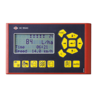
Lists possible display readouts for the system, including volume rate, speed, and trip registers.
Overview of the system's functions, including boom section control and alarm features.
Explains the ISOBUS system wiring for trailed and self-propelled sprayers.
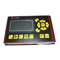
Describes types of ISOBUS display terminals: physical buttons vs. touchscreen.
Details the two types of ISOBUS display terminals: physical buttons and touchscreen.
Description of ISOBUS terminals with physical function buttons.
Description of ISOBUS terminals with touchscreen interface, like the HC 9500.
Explains the layout of the ISOBUS terminal and its virtual terminal buttons.
Lists and describes the functions of the virtual terminal buttons on the ISOBUS display.
Explains common symbols found on VT (Virtual Terminal) displays and their meanings.
Explains how preset keys provide quick access to vital information while spraying.
Describes how soft keys control optional features and activate submenus.
Details the use of navigation keys for setup and changing values on the ISOBUS Terminal.
Identifies numeric keys as the standard keypad for the ISOBUS terminal.
Illustrates the structure and functions of the soft keys menu.
Explains the SetBox controls secondary functions and its grouping into control areas.
Describes the HC 6300 Grip as an ergonomic remote unit for operating sprayer functions.
Explains the basic steps for selecting menus on the ISOBUS terminal.
Provides a step-by-step example of editing tank contents on the ISOBUS VT.
Describes the extended menu for dealer setup and its parameters.
Details the system's functions, including auto functions and end nozzles.
Explains that soft key buttons are used for End Nozzle functions.
Explains setup and operation of optional end nozzles or Bi-jet.
Explains the DynamicFluid4 system for continuous pressure regulation.
Describes the sprayer driver's selection of three modes and their corresponding icons.
Illustrates the regulation valve function in different scenarios during spraying.
Details the SafeTrack steering mechanism for trailed sprayers and influencing factors.
Explains the functions of HARDI® AutoSectionControl for managing sections and recording area.
Covers the full menu structure listing all available menus and their functions.
Presents a detailed hierarchical list of all menus and their descriptions.
Instructions for installing control unit brackets in the tractor cabin.
Details on mounting brackets, tubes, and spacers for control units.
Information on utilizing the tube to fit the printer on Controller brackets.
Describes the location, type, and adjustment of the speed transducer.
Provides a step-by-step guide for setting the clock on the ISOBUS Terminal.
Covers system start-up and initial prompts for date and time.
Explains the system's self-initiation process and initial prompts upon turning ON.
Explains how to customize display readouts on ISOBUS terminals (boxes A-F).
Details how to select and customize display readouts for different boxes.
Details how to configure the ESC key as a softkey or physical button.
Outlines the steps for setting up the sprayer before starting a spray job.
Lists essential steps for preparing the sprayer before a spray job.
Explains how to set and read the volume rate on the HC 9500 ISOBUS terminal.
Instructions on how to access and view the current volume rate.
Provides steps to modify the volume rate using the Controller or SetBox.
Explains how to use manual dosage mode via the SetBox pressure buttons.
Explains how registers are identified, saved, read, and selected.
Instructions for reading the total data from all registers (register 99).
Steps to access and read data from the currently active register.
Procedure for selecting a different register for the spray job.
How to reset a register using the Escape key.
Instructions for entering tank contents if no tank gauge is fitted.
Explains setting air volume and angle in two positions: Headwind and Tail wind.
Steps to store manual presets for headwind and tailwind settings.
How to set TWIN presets to shift automatically based on main ON/OFF.
Describes the start-up procedure for spraying with DynamicFluid4.
Explains the meaning of different LED colors on the regulation valve.
Details how spray pressure is controlled by the regulation valve with FlexCapacity pumps.
Overview of daily settings including volume rate, tank contents, and register selection.
Explains volume rate as application rate and how it's measured.
Instructions for entering tank contents if no tank gauge is fitted.
Describes register usage for individual areas and tallying trips.
General information on navigating menus and mastering keystrokes.
Guides the user on mastering keystrokes and navigating to specific menus.
Explains how to customize display readouts on ISOBUS terminals (boxes A-F).
Details how to configure the ESC key as a softkey or physical button.
Covers setup for automatic functions like Main ON/OFF and Foam Marker.
Explains setting the Controller for automatic main ON/OFF based on speed.
Details automatic operation of the HARDI® Foam marker via main ON/OFF valve.
Allows selection of automatic or manual shifting for TWIN presets.
Enables VRA/Remote or AutoSectionControl from external sources.
Instructions for setting the Controller's date and time for register recording.
Allows setting user-selectable alarms and explains warning display.
Overview of calibration procedures for various sensors and system parameters.
Explains the process for calibrating speed sensors (sprayer, tractor, radar).
Guides on how to select speed calibration menus based on the sensor type.
Explains choosing between theoretical speed constant and practical calibration.
Details calculating the theoretical speed constant (PPU) based on tire dimensions.
Describes practical speed calibration by driving a measured distance.
Explains theoretical and practical methods for calibrating the flow transducer.
Covers changing the theoretical flow constant (PPU) for different flow sensor housings.
Describes comparing individual nozzle output with actual output for correction.
Explains calibrating tank contents by emptying the tank and calculating dispensed volume.
Covers setting boom width, number of sections, and nozzles per section.
Instructions for setting the total spray boom width.
Steps to set the number of spray boom sections.
Procedure to set the correct number of nozzles per section.
Instructions for setting up end nozzles or Bi-jet to correspond with boom nozzles.
Sets the distance from hitch eye to sprayer axle for AutoSectionControl.
Sets the distance from sprayer wheel axle to boom for AutoSectionControl.
Adjusts pressure regulation valve sensitivity based on sensor inputs.
Defines plumbing resistance based on flow housing choice.
Used when stopped or if speed sensor is defective to maintain pressure.
Enters nozzle size manually if flow or pressure sensors are faulty.
Configuration for dual line second nozzle (not applicable in North America).
Selects the type of nozzle to be used for spraying.
Sets a code for special machines or applications, consult HARDI® Service Center.
Instructions for setting up the Tank Gauge, only if fitted.
Sets the correction factor for the specific gravity of the sprayed liquid.
Details when and how to calibrate the HARDI® Tank Gauge if factory calibration is inaccurate.
Step-by-step guide for custom calibration of the tank gauge.
Allows selection of preloaded factory calibration for HARDI® tanks.
Reads and accepts the frequency (Hz) at empty tank for calibration.
Explains adjustments for Track setup based on tractor, sprayer, and practices.
Details SafeTrack operation via SetBox, including align, auto, and manual buttons.
Instructions for entering the track width, measured wheel center to wheel center.
Explains entering the tractor drawbar length for sprayer attachment.
Adjusts the non-regulation zone for sprayer stability when driving straight.
Adjusts hydraulic damping to prevent boom damage and ensure stability.
Compensates for front potentiometer offset to align sprayer with tractor.
Adapts track regulation to tractor and sprayer hydraulics for optimal performance.
Provides access to helpful tools like measurement, service intervals, and testing.
Functions for measuring distance, area, working width, stopwatch, and alarm clock.
Displays programmed service intervals and nozzle check reminders.
Instructions on how to reset service intervals after maintenance.
Indicates a reserved menu function that is not used.
Allows testing of transducers, active keys, and system components.
Enables simulation of speed for specific purposes when the controller is active.
Bypasses system sensors for manual alignment or boom folding in emergencies.
Checks sensor status and voltages during track alignment.
Checks sensor status and voltages during boom folding.
Shows communication status between units like Controller, Jobcom, and Track.
Provides functions for printing data and performing data dumps.
Details options for printing single registers, all registers, and system configurations.
Enables data dump to an office printer using HyperTerminal function.
Instructions for proper storage of the sprayer and its components.
Guidance on disconnecting power supply and protecting components during storage.
General guide to troubleshooting system problems before contacting a dealer.
Provides a schematic for troubleshooting common system issues like flow and speed.
Recommends checks for clogging in valves and hoses to avoid contamination.
Provides steps to check for external leaks in the sprayer system.
Lists and illustrates the location of various sensors and components on trailed sprayers.
Lists and illustrates the location of various sensors and components on self-propelled sprayers.
Explains fault codes, their display text, criteria, and help text.
Guides on emergency situations and operation when sensors fail.
Describes checking Computer CAN status in case of system errors.
Explains how the system operates with reduced performance when sensors fail.
Steps for testing the fluid system, pump condition, and valve leakages.
Covers fine-tuning the flow constant and understanding pin & wire connections.
Explains how to adjust the flow transducer PPU for accurate volume readings.
Details the pin and wire connections for AMP Super Seal connectors.
Provides steps for testing the flow transducer using a multimeter.
Details testing the speed transducer using a multimeter and metallic object.
Lists technical specifications for the ISOBUS VT system.
Provides flow ranges and PPU values for different flow sensor housings.
Details types of plugs and fuses used in the system.
Information on disposal of electronics and packaging materials.
Guidelines for recycling and disposing of electronic components.
Information on the environmental compatibility of packaging materials.
Provides a chart for recording flow and speed constant values.
A template for recording flow PPU and speed PPU values.
Details the limited warranty terms, conditions, and customer responsibilities.
| Category | Controller |
|---|---|
| Display | Touchscreen |
| Operating System | Linux |
| Connectivity | CAN, USB, Ethernet |
| Protection Class | IP65 |
| ISOBUS Compatibility | ISO 11783 |
| Display Size | 12.1 inch |
| Power Supply | 12V/24V DC |
| Operating Temperature | -20°C to +50°C |