Do you have a question about the Hardi HC6500 and is the answer not in the manual?
Provides details for product, service, warranty, and direct contact.
Explains the meaning of DANGER, WARNING, and ATTENTION symbols.
Covers reading the manual, keeping children away, and safe operation practices.
Provides the toll-free number for the US Poison Control Center.
Reminds users to keep a list of chemicals in use.
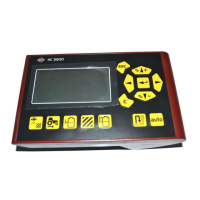
Describes the HC 6500 controller, its CAN system, and key hardware.
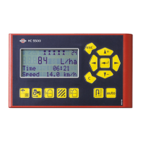
Details the display, readouts, functions, alarms, and Grip controls.
Explains how LookAhead predicts settings and improves regulation.
Covers necessary tractor gearbox and nozzle selection.
Introduces steering mechanisms for sprayer stability.
Discusses influencing factors and driving advice.
Lists and illustrates system components and their connections.
Explains Preset, Soft, Navigation, and Numeric keys.
Details the use of the built-in help function.
Identifies the keys on the Terminal HC 6500.
Explains the various icons displayed on the screen.
Describes how to select display illumination modes.
Lists secondary functions controlled by the SetBox module.
Details the functions operated via the ergonomic Grip controller.
Explains the display lines and how to interpret symbols.
Describes basic menu navigation and value entry.
Provides an example of entering tank contents.
Warns against altering extended menu settings without instruction.
Describes setup and use of optional end nozzles and TWIN presets.
Explains the automatic boom section control feature.
Guides on selecting a suitable location for control units.
Details the installation of brackets and mounting tubes.
Specifies voltage, polarity, wire gauge, and fuse requirements.
Illustrates harness connections to the tractor battery.
Describes connecting speed sensors for sprayer and tractor.
Explains the installation and function of the foot pedal remote.
Lists the main components involved in initial setup.
Shows the basic connection layout for system startup.
Describes the controller's startup sequence and prompts.
Explains the prompt for nozzle choice when LookAhead is enabled.
Details testing pressure regulation response to speed changes.
Explains how the valve rotates based on speed adjustments.
Details testing pressure regulation response to section changes.
Explains the setup for optional pressure-based regulation.
Describes methods to change the volume rate.
Explains manual dosage and switching to automatic mode.
Explains how to manually update the tank contents readout.
Notes automatic readout when a tank gauge is fitted.
Explains how to view, select, and reset registers.
Describes selecting a different nozzle without restarting the controller.
Explains how to select data to be displayed in specific screen areas.
Provides descriptions for various data fields that can be shown on the display.
Details setting up automatic main ON/OFF based on speed.
Explains settings for automatic foam marker control.
Describes options for automatic or manual TWIN preset shifting.
Notes features not applicable in North America.
Explains how to enable these features and connect external sources.
Details requirements like JobCom computer and specific ports.
Guides on setting the time format and entering the current time.
Explains how to set the current date and year.
Lists available alarms and their setup parameters.
Explains how warnings are displayed and how to adjust audio feedback.
Describes how to assign names to registers for easier identification.
Explains how to navigate to the speed calibration options.
Outlines selecting between theoretical constant or practical calibration.
Details entering the theoretical speed constant value.
Describes the hands-on procedure for calibrating speed.
Discusses choosing between theoretical and practical flow calibration methods.
Explains how to input the theoretical flow constant.
Details the procedure for calibrating flow using individual nozzle outputs.
Introduces the tank method for flow calibration.
Describes the steps for calibrating flow using the tank method by measuring volume.
Guides on configuring boom width and the number of sections.
Explains how to input the number of nozzles for each section.
Details the setup for optional end nozzles or Bi-jets.
Explains how to adjust the regulation constant for optimal performance.
Guides on setting the specific gravity correction factor.
Details the steps for custom calibration if factory settings are inaccurate.
Recommends verifying flow calibration accuracy.
Describes filling the tank and measuring water levels.
Emphasizes the need for proper sprayer levelling during calibration.
Details emptying the tank and correcting the displayed volume.
Explains how to select factory calibration and its prerequisites.
Guides on setting the offset for an empty tank.
Provides general information on track setup depending on tractor and practices.
Describes the manual, auto, and align modes of SafeTrack.
Explains how to adjust dead zone and damping for stability.
Details aligning the sprayer and adjusting track sensitivity.
Describes the procedure to find steering offset values.
Explains the process of finding steering gain values.
Details the confirmation message and how to exit calibration.
Refers to emergency track procedures.
Explains how to start the LookAhead calibration process.
Details the steps for calibrating LookAhead at specific speeds.
Introduces the trip meter and lists available measurement submenus.
Explains how service intervals are programmed and displayed.
Lists specific service tasks and their recommended intervals.
Guides on how to reset individual service intervals after completion.
Explains how to select and activate items for testing sensors.
Lists the different sensors and functions that can be tested.
Describes how and why to use the speed simulation function.
Explains the bypass function and checking sensor status during emergencies.
Details manual steering and boom folding procedures for emergency situations.
Lists submenus to verify communication between system units.
Lists the types of data that can be printed from the logbook.
Shows examples of printed register data and system configuration.
Explains how to transfer logbook data to an external printer.
Lists necessary hardware and software settings for data transfer.
Details the hierarchical structure and available functions of the soft keys.
Provides instructions for storing the equipment during the off-season.
Guides users to check Computer CAN status for error diagnosis.
Presents a table detailing alarms, fault criteria, and operations disabled.
Lists specific fault codes, their causes, and help text.
Describes troubleshooting for illegal actions and waiting states.
Lists various system warnings and their potential causes.
Lists specific errors and reminders for system components.
Describes alerts related to sensor failures and boom issues.
Explains how to fine-tune the flow constant based on actual usage.
Provides pin assignments for connectors.
Details the steps for testing the speed transducer.
Lists key technical specifications like voltage, temperature, and memory.
Provides data on flow ranges and PPU values for different housings.
Identifies the various plugs and fuses within the system.
Advises on the proper disposal and recycling of electronic components.
Describes the environmentally compatible nature of the packaging.
Provides a table for logging important calibration and setting values.
Outlines the duration and coverage of the limited warranty.
Details conditions that void the warranty and customer obligations.
States requirements for warranty work approval and claim submission.
Specifies procedures for returning parts for warranty settlement.
| Brand | Hardi |
|---|---|
| Model | HC6500 |
| Category | Controller |
| Language | English |