4 - System setup
4.3
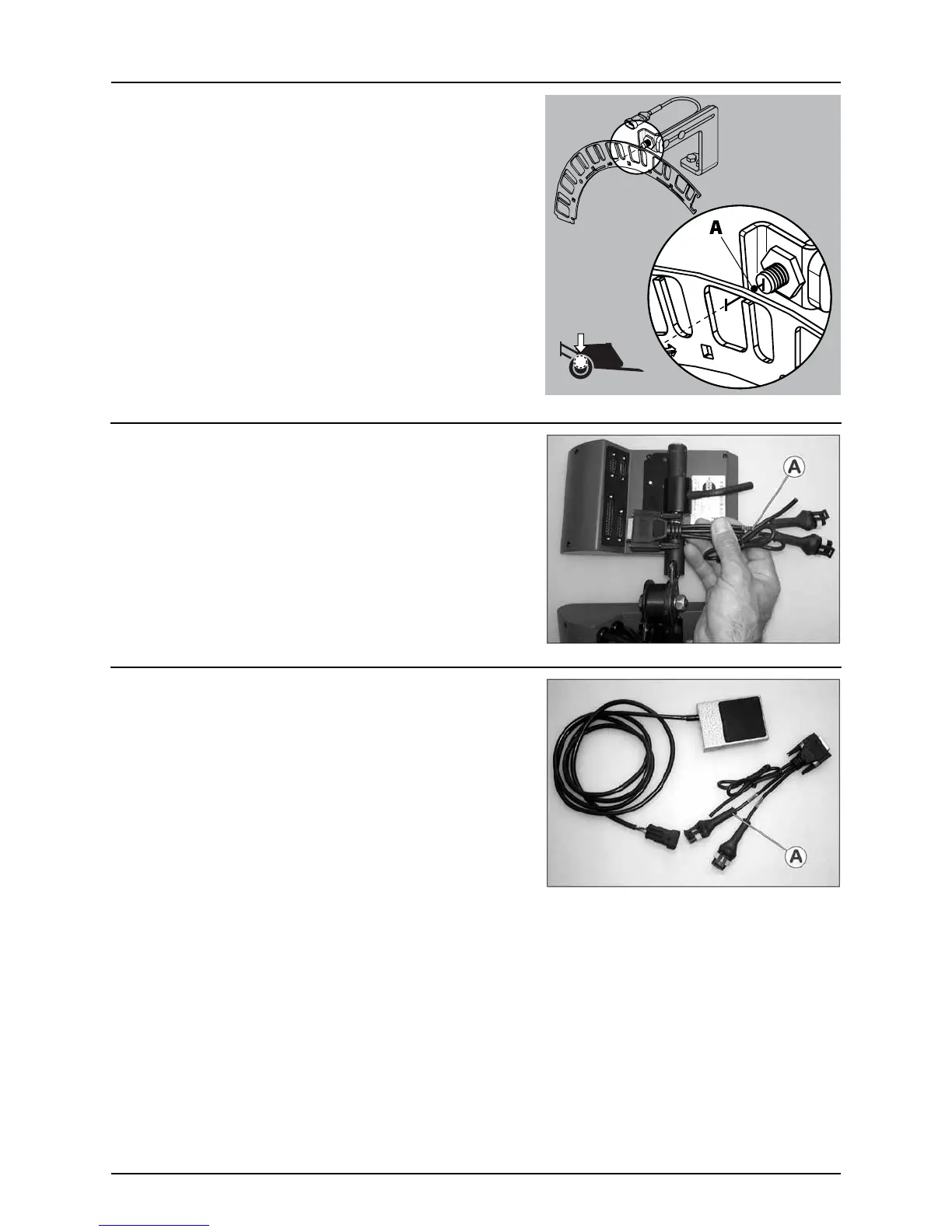
Speed transducer for sprayer
The speed transducer is located at the inside of the sprayer’s right wheel.
It is an inductive type that requires a metallic protrusion to pass by it to
trigger a signal. A speed ring is used to trigger the transducer. It should
be adjusted so the transducer is placed in the center of the holes in the
speed ring (vertical direction). Recommended distance between
protrusion and transducer (A) is 1/8” to 1/4” (3 to 6 mm). Check
throughout the entire circumference. Correct adjustment is indicated
by a constant blinking from the transducer when the wheel rotates.
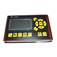
Speed transducer for tractor
It is possible to connect a speed sensor from tractor gearbox or
radar/GPS to the controller. A speed/switch harness (A) and extension
cable are needed to connect the speed transducer to the
Controller/Terminal.
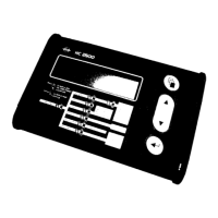
Foot pedal remote ON/OFF (optional)
Note the following if the Foot pedal remote is to be fitted.
Remote ON/OFF switch has to be activated from the extended menu at
installation. The HARDI® Service center does this.
The speed/switch harness (A) is connected to the Controller/Terminal.
Connect the plug from the Foot pedal ON/OFF to the correct connector
on harness (A).
μ
ATTENTION! The main ON/OFF valve switch at Grip overrides all remote switches. It must be set to ON for the optional
Remote ON/OFF switch to function.