Do you have a question about the Hardi 5500 and is the answer not in the manual?
Lists important safety precautions including reading the manual, turning off power, using clean water, and keeping children away.
Specifies voltage, wire polarity, wire cross-section, and notes on connecting to battery or starter motor.
Details the tractor pillar bracket, tubes, and spacer for mounting components, advising checking tractor instructions.
Recommends placement to the right of the driver seat, secured from movement, and mounting the Controller in the tractor cabin.
Explains fitting the 12 Volt printer using supplied tubing and protecting the Controller/Spray Box from moisture.
Details the inductive speed transducer, its requirement for metallic protrusion, and recommended distance for signal triggering.
Explains the optional foot pedal remote installation, activation, and override by the main ON/OFF switch for functionality.
Details the process of setting the clock for register enablement, including prompts, 24/12 hour format, and date entry.
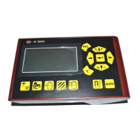
Explains the function of each navigation key for menu setup, scrolling, increasing/decreasing values, and entering/escaping menus.
Provides a general overview of keystrokes and display readings, explaining how to navigate and alter values within menus.
Explains setting the main ON/OFF function based on speed, allowing concentration on driving, and warning about transport mode.
Details setting the Foam marker to operate automatically with the main ON/OFF valve and options for race-track or round-and-round spraying.
Details the process for calibrating speed sensors (Sprayer, Tractor, Radar) theoretically or practically for accurate speed readings.
Explains setting the theoretical flow constant (PPU) and provides approximate PPU values for different HARDI flow housings.
Describes the nozzle method for flow calibration, comparing individual nozzle output to actual output using a calibration jug.
Details the tank method for flow calibration by emptying the tank and comparing displayed volume to actual dosed quantity.
Explains calibration for sprayers with circulation liquid systems, referencing 'Flow 1' as a reference for 'Flow 2'.
Details entering the boom width in meters, which is essential for area measurement and other calculations.
Explains setting the number of boom sections, typically two (left and right) for orchard sprayers.
Explains setting end nozzle coverage equivalent to boom nozzles for accurate volume application comparison.
Explains setting the correction factor for the specific gravity of sprayed liquid, with default value 1.000.
Guides through the steps of calibrating the tank gauge by setting fill level, confirming sprayer level, and emptying the tank.
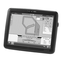
Describes the electronic 'measuring tape' function for measuring distance and area if implement width is set.
Details programming four service intervals and a nozzle check reminder, including actions and reset procedures.
Explains using the clock as a timer, with functions to start, stop, and clear the value.
Details setting the clock to provide an alarm when a specific time is reached, using navigation keys to set the alarm.
Explains testing transducers (flow, speed, sensors) by activating them and checking for signal detection.
Describes simulating speed for certain purposes, allowing a two-figure value entry that remains until restart or reset to '0'.
Details printing specific registers, all active registers, or the entire controller configuration via the 12-volt printer.
Explains printing data to an office printer using Hyper Terminal, requiring a cable connection and 12-volt power supply.
Explains UCR calibration based on canopy height, width, and row length, and how to adjust crop width and height.
Details setting maximum tank contents using a filling meter or transducer, triggering an alarm when filled.
Explains the optional fill meter function for setting fill level limits and the behavior of actual contents and filled volume display.
Advises disconnecting power, protecting from moisture, and removing Controller/Spray Box if tractor lacks a cabin.
Explains operating the control unit without the Controller by disconnecting it, allowing spraying to continue if the Controller is faulty.
Explains how to 'fine tune' the flow transducer PPU using a formula to adjust displayed volume to match actual sprayed volume.
Provides step-by-step instructions for testing the flow transducer using a multimeter, detailing wire connections and expected voltage readings.
Details testing the speed transducer with a multimeter, including wire connections, proximity testing, and expected voltage readings.
Presents a table of flow ranges for different HARDI flow housings, including orifice size and approximate PPU values.
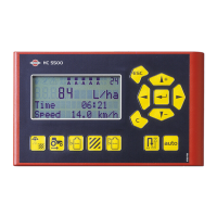
Explains the meaning of symbols and readouts appearing on the first line of the Controller display for status and warnings.
Details the functions of navigation keys and spray box switches, including preset functions and shortcuts.
Outlines essential initial steps including entering boom data, flow calibration constant, and volume rate before operation.
| Brand | Hardi |
|---|---|
| Model | 5500 |
| Category | Controller |
| Language | English |