6
HARDI CONTROLLER 5500
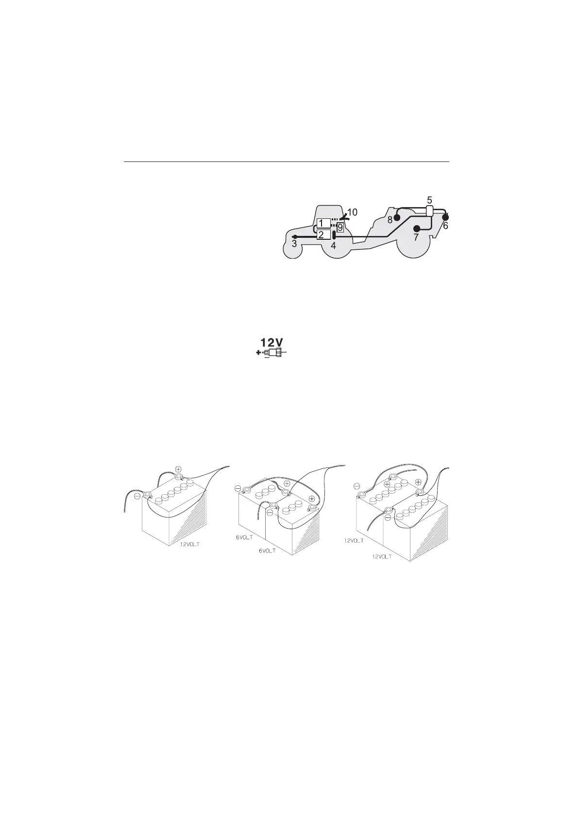
System description
1. Controller
2. Spray Box
3. To 12 Volt power supply
4. Multi wire plug and cable
5. Junction box (on sprayer)
6. Flow transducer
7. Speed transducer
8. Tank contents transducer (optional)
9. Printer (optional)
10. Harness for tractor speed/area switch/foot remote ON/OFF
Power supply
The power supply is 12 Volt DC.
Brown wire is positive “⊕”.
Blue wire is negative “-”.
Power supply must come directly from the battery. The wires must have a
cross-sectional area of at least 1.0 mm
2
to ensure sufficient power supply.
NOTE: Do not connect to the starter motor or generator/alternator.
Warranty is void if this is done.
Use the HARDI Electric distribution box (Ref. no. 817925) if the tractor has
a doubtful wiring.
T165-0002