Do you have a question about the Hardi HC2500 and is the answer not in the manual?
Details the HM 1500 Monitor setup with manual control unit (BK, BK/EC).
Explains the HM 1500 Monitor setup with manual control and spray box.
Details the HM 1500 Monitor setup with electric control unit (EVC, CB).
Details the speed transducer installation and function on a tractor.
Details installation for revolutions and area-meter transducers.
Describes the analog transducer, used for pressure measurement.
Guidance on routing and using transducer cables to prevent damage.
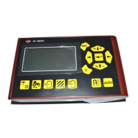
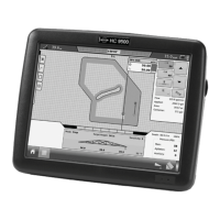
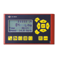
Explains the display components and keys during system startup.
How to view the currently selected volume rate on the display.
Procedure to adjust the desired volume rate for alarms on HM 1500.
How to change the volume rate on the HC 2500 controller.
Explanation of the function of general keys for menu navigation.
Option to select data to be displayed on screen.
Option to change the indicated tank contents.
Access to calibration menus for system parameters.
Option to set alarm parameters for the system.
Select registers to record area covered and volume sprayed.
Test the functionality of system transducers.
Show readout from optional analog transducer.
Show revolutions data.
Show driving speed.
Show the active boom size.
Procedure for setting boom sections and width for calibration.
Instructions for calibrating the flow transducer.
Method to change the flow constant theoretically.
Practical method for flow calibration using nozzle output comparison.
Practical method for flow calibration using tank emptying.
Procedure for setting the theoretical speed constant (UPP).
Practical method for calibrating the speed transducer.
Steps for measuring distance and correcting speed display.
Functionality for selecting and managing area trip meters.
Procedure to test the flow sensor functionality.
Procedure to test the speed sensor functionality.
Test the functionality of the area-meter switch.
Procedure to test the revolutions sensor functionality.
Procedure to test an optional transducer.
Procedure to adjust the flow transducer's PPU value for accuracy.
Testing procedure for inductive type speed transducers.
Testing procedure for Hall element speed transducers.
Details flow ranges and PPU values for different flow transducer housings.
Information regarding recycling of packaging materials.
Default settings for HC 2500 and HM 1500 systems.
| Brand | Hardi |
|---|---|
| Model | HC2500 |
| Category | Controller |
| Language | English |