EasyManua.ls Logo

Harman Kardon AVR 5550 Service Manual

Harman Kardon AVR 5550
98 pages
To Next Page IconTo Next Page
Page #1 background imageLoading...
Page #1 background image
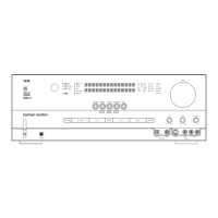
AVR 5550 Audio/VideoReceiver
SERVICE MANUAL
AVR 5550
ready
LOGIC 7
VMAx
Power for the Digital Revolution
®

Other manuals for Harman Kardon AVR 5550

Question and Answer IconNeed help?

Do you have a question about the Harman Kardon AVR 5550 and is the answer not in the manual?

Harman Kardon AVR 5550 Specifications

General IconGeneral
TypeAV Receiver
Channels7.1
Total Harmonic Distortion0.07%
Input Sensitivity200 mV
Signal-to-Noise Ratio100dB
Speaker Load Impedance8 ohms
Input Impedance47 kOhms
Frequency Response20 Hz - 20 kHz
Digital Inputs3 x optical, 2 x coaxial
Video ConnectionsComposite, S-Video
Power Output (Stereo)110W per channel (8 ohms, 20Hz - 20kHz, 0.07% THD)

Summary

Technical Specifications

Audio Section Specifications

Details audio performance metrics including power output, input sensitivity, and frequency response.

FM Tuner Section Specifications

Details FM tuner performance metrics like frequency range, sensitivity, and signal-to-noise ratio.

AM Tuner Section Specifications

Details AM tuner performance metrics like frequency range, sensitivity, and signal-to-noise ratio.

Video Section Specifications

Details video signal characteristics including format, input/output levels, and frequency response.

General Specifications

Covers general unit specifications like power requirements, dimensions, and weight.

Exploded View

Part List Exploded View AVR5550

Front Board AVR5550 Parts List

Key Board AVR5550 Parts List

DSP Board AVR5550 Parts List

Processor Board AVR5550 Parts List

Main Board AVR5550 Parts List

Surround Board AVR5550 Parts List

Mech AVR5550 Parts List

Packing AVR5550

AVR325/525 Alignment Specification

Main Board Bias Adjustment

Bias adjustment for Front Left, Surround Left, Front Right, and Surround Right channels.

Back Surround Board Bias Adjustment

Bias Adjustment for Surround Channels

Bias adjustment for SBL, Center, and SBR channels.

Wiring Diagram

Block Diagram

Schematic Diagram - Front Board

Schematic Diagram - DSP Board

Schematic Diagram

AVR 525/325 Main Amp Schematic Diagram

AVR 525/325 Center SB Amp Schematic Diagram

AVR 525/325 Supply Schematic Diagram

Schematic Diagram

Schematic Diagram - Video Board

Composite/Super Video Part

Circuitry for composite and super video signal processing.

Component Video Part

Circuitry for component video signal processing.

Related product manuals