EasyManua.ls Logo

Harman Kardon AVR40 User Manual

Harman Kardon AVR40
70 pages
To Next Page IconTo Next Page
Page #1 background imageLoading...
Page #1 background image
Question and Answer IconNeed help?

Do you have a question about the Harman Kardon AVR40 and is the answer not in the manual?

Harman Kardon AVR40 Specifications

General IconGeneral
TypeAV Receiver
Input Sensitivity200mV
THD0.08%
4K SupportYes
Signal-to-Noise Ratio100 dB (IHF-A)
Speaker Impedance8 Ohms

Summary

SPECIFICATIONS

LEAKAGE TEST

DISASSEMBLY PROCEDURES

CIRCUIT DESCRIPTION

CPU Circuits (IC 301)

Overview of the CPU's role, pin functions, and block diagram.

INPUT/OUTPUT TERMINAL FUNCTIONS

Explanation of functions for each input/output terminal pin.

PROTECTION CIRCUITS

SPEAKER PROTECTION CIRCUIT

Details the circuit protecting speakers from abnormal current.

SURROUND CIRCUITS

DOLBY PRO-LOGIC CIRCUIT (MOVIE)

Description of the Dolby Pro-Logic decoder and its operation.

ALIGNMENT PROCEDURES

Equipment Required

Lists tools for alignment.

AM IF and RF Alignment

Steps for aligning the AM tuner's intermediate and radio frequency sections.

FM IF Alignment

Steps for aligning the FM tuner's intermediate frequency section.

TROUBLESHOOTING

GENERAL UNIT PARTS LIST

PRODUCT SAFETY NOTICE

Important safety warnings regarding component replacement and service.

ELECTRICAL PARTS LIST

IC FUNCTIONAL BLOCK DIAGRAM

IC102, IC103: LC7821

Functional block diagram for the LC7821 integrated circuit.

IC501: LC4966B

Functional block diagram for the LC4966B integrated circuit.

SCHEMATIC DIAGRAM (I)

CONTROLS AND FUNCTIONS

Front Panel Controls Overview

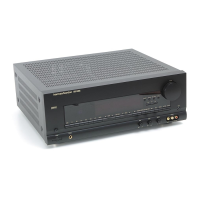
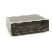
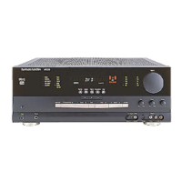
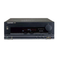
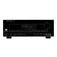
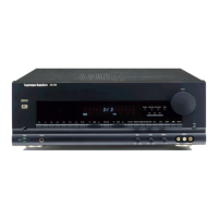
Explanation of front panel buttons, knobs, and indicators.

Tuning and Display Functions

Details on tuner operation, memory, and display features.

BLOCK DIAGRAM

GENERAL UNIT EXPLODED VIEW

PRINTED CIRCUIT BOARDS

SCHEMATIC DIAGRAM (II)

SCHEMATIC DIAGRAM (V)

SCHEMATIC DIAGRAM (VII)

WIRING DIAGRAM

Related product manuals