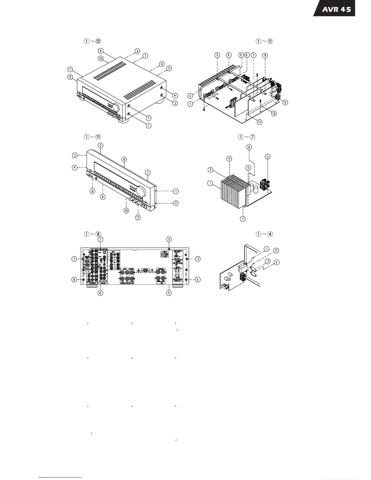
DISASSEMBLY PROCEDUREDISASSEMBLY PROCEDURE
1. Removing the top cover, and
Remove screws
4. Removing the main PCB block, and
Remove screws
2. Removing the front panel, and
Remove screws
5. Removing the power PCB block, and
Remove
3. Removing the rear panel, and
Remove screws
1. Remove all of the screws on Rear panel.
2. Remove the Rear panel.
3. Remove PCB Brk t and Guide
5. Remove the Main PCB block.
Brk t from Main Ass y.
4. Remove all of the screws that connect with main Ass y.
1. Remove 4 screws on Rear panel.
2. Remove the Rear panel.
3. Remove PCB Brk t and Guide
4. Remove the SUB PCB block.
Brk t from Main Ass y.
1. Remove Main
2. Remove volume and rotary knob from the front
3. Remove all of the screws on back side of Front function PCB.
4. Remove the Front function PCB.
Ass y.
Ass y.
1. Remove PCB Brk t and Guide
3. Remove the POWER PCB block.
Brk t from Main Ass y.
2. Remove 4 screws for Power PCB mounting
6. Removing the sub PCB block, and
Remove screws
MAIN AMP PCB BLOCKMAIN AMP PCB BLOCK
SUB PCB BLOCKSUB PCB BLOCK
FRONT PCB BLOCKFRONT PCB BLOCK
POWER PCB BLOCKPOWER PCB BLOCK
 Loading...