- 11 -
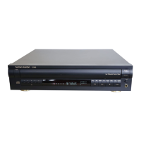
9. PCB-5 (Front) REMOVAL
1. Remove screws to in Fig.9
2. Pull-out the PCB-5 from the Front Panel.
10. PCB-6(Headphone) Removal.
1. Remove screws to in Fig.9
2. Pull-out the Rotate Volume in Fig.1 from the PCB-6(Headphone).
3. Remove the PCB-6 from the Front Panel.
11. PCB-7(REC Volume) Removal.
1. Remove screws to in Fig.9
2. Pull-out the Rotate Volume in Fig.1 from the PCB-7(REC Volume).
3. Remove the PCB-7 from the Front Panel.
➍
➎➋
➊
➌
➏
➐
<Fig 9>
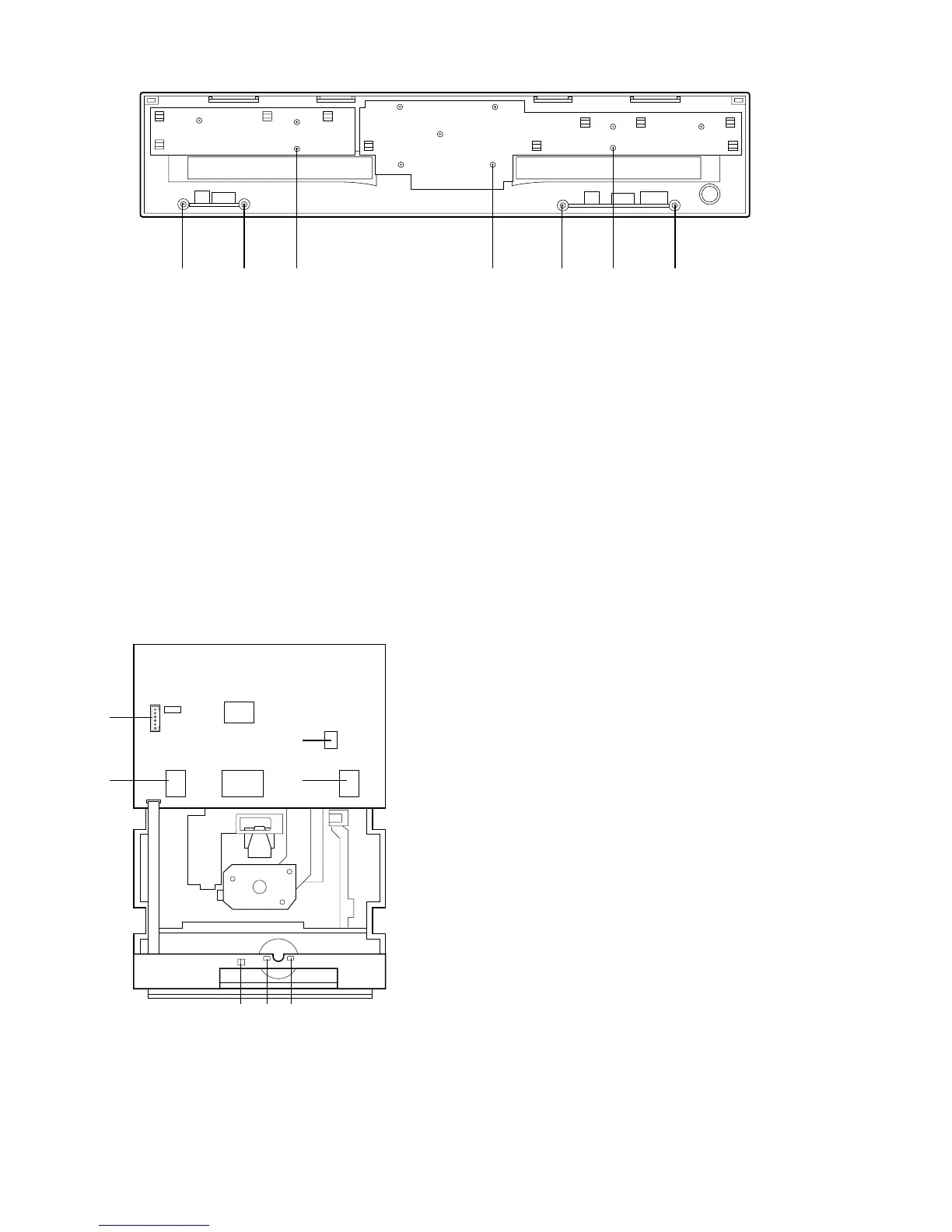
1. unsolder the motor lead to which are connected to
PCB-3.
2. Pull-out the PCB-3 by hook-off to in Fig.10
from the MECHA-1(CDP)
3. Detach the connector to in Fig.10
4. Remove the PCB-3 from the MECHA-1(CDP).
12. PCB-3(CDP) REMOVAL
<Fig 10>
➊
➎
➐
➏
➋
➍➌
➌➍
➊➋
➎➐
➊➌
➏➐
➏
➍➎
➎

 Loading...