- 26 -
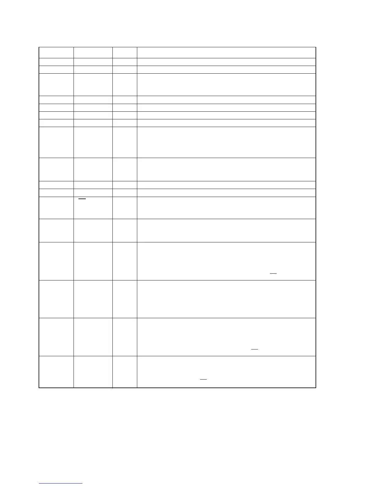
➁ Pin Descriptions
No. Pin Name I/O FUNCTION
1 AINR+ I Right channel analog positive input pin
2 AINR- I Right channel analog negative input Pin
3 VREF O Voltage Reference output pin (VA-2.6V)
Normally connected to VA with a 0.luF ceramic capacitor in
parallel with a 10uF electrolytic capacitor.
4 VA --- Analog section Analog Power Supply, +5V
5 AGND --- Analog section Analog Ground
6 AINL+ I Left channel analog positive input pin
7 AINL- I Left channel analog negative input pin
8 TST1 Test pin (Pull-down pin)
10 TST2 Should be left floating.
11 TST3
14 TST4
9 HPFE I High Pass Filter Enable pin(Pull-up pin)
"H": ON
"L": OFF
12 VD --- Digital section Digital Power Supply pin, +5V
13 DGND --- Digital section Digital Ground pin
16
PD
I Power Down pin
"L" brings tne device into power-down mode. Must be done
once after power-on.
17 MCLK I Master Clock input pin
CMODE="H" : 384fs
CMODE="L" : 256fs
18 SCLK I/O Serial Data Clock pin
Data is clocked out at the falling edge of SCLK.
Slave mode: 64fs clock is input usually.
Master mode: SCLK outputs a 64fs clock.
SCLK stays low during the power-down mode(PD="L").
19 LRCK I/O L/R Channel Clock Select pin
Slave mode: An fs clock is fed to this LRCK pin.
Master mode: LRCK output an fs clock.
LRCK goes "H" at SMODE2="L" and "L" at SMODE2='"H"
during reset when SMODE1 "H".
20 FSYNC I/O Frame Synchronization Signal pin
Slave mode: When "H", data bits are clocked out on SDATA.
As I
2
S slave mode ignores FSYNC, it should hold "L" or "H".
Master mode: FSYNC outputs 2fs clock.
Stay low during the power-down mode(PD="L")
21 SDATA O Serial Data Output pin
Data are output with MSB first, in 2's complement format.
After 20 bits are output it turns to "L". It also remains "L"at a
power-down mode(PD="L").

 Loading...