- 27 -
No. Pin Name I/O FUNCTION
22 CMODE I Master Clock Selection pin
"L": MCLK=256fs
"H": MCLK=384fs
23 SMODE1 I Serial Interface Mode Select pin
15 SMODE2 I Defines the directions of LRCK, SCLK and FSYNC pins and
Output Data Format. SMODE2 is pull-down pin.
SMODE1 SMODE2 MODE LRCK
L L Slave mode: MSB justified: :H/L
H L Master mode: Similar to I
2
S :H/L
L H Slavemode:I
2
S :L/H
H H Master mode:I
2
S :L/H
24 VB --- Substrate Power Supply, +5V
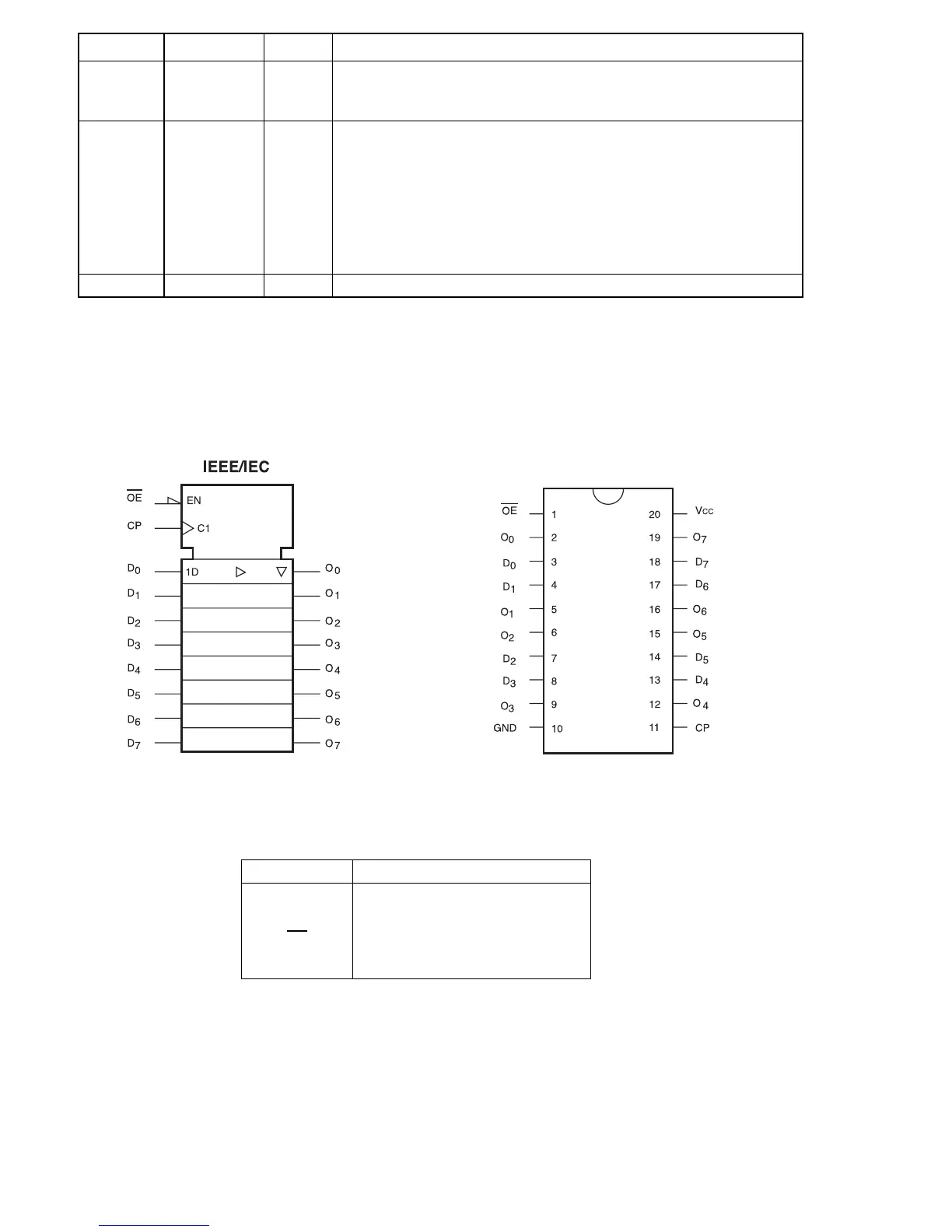
9. 74VHC374
➀ Logic Symbol ➁ Connection Diagram
➂ Pin Descriptions
Pin Names Description
D
0
-D
7
Data Inputs
CP Clock Pulse Input
OE 3-STATE Output Enable Input
O
0
-O
7
3-STATE Outputs

 Loading...