15
3-90-00674R28_12/13
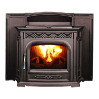
Fig.32
Installation
The green wire with a female terminal is the stove body
ground.SeeFig.32
On the combustion air inlet box there is a male terminal
ground.
If service is performed on this stove, this ground
connection must be the rst one on and the last one off.
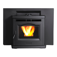
Fig.33
15. Installthecastsidepanelsbyslidingthemdownover
thelaseredhingepin.Note:Checkforrotationalswing,
butnishwiththemintheopenposition.Thecastside
panels may need adjustment after the stove body is
latchedintoplaceandthefrontdoorisclosed.
Connecting the power cord
Thewhitefromthemountingframeconnectstothewhiteof
theinsertbody.Theblackfromthemountingframeconnects
tothebrownoftheinsertbody.
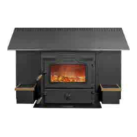
16. Placethestovebodyonthemountingshellgasketedrails
andinsertthebodyintotheopeningfarenoughthatit
can'ttipout.Note:Aservicerailkit(Part#1-00-08007),
orapairof2x4'ssupportedinfrontofthehearthwill
makethisjobeasier.SeeFig.31.
17. Completethefollowingelectricalconnections(CAUTION:
Disconnectthepowercord.)There are 5 connections
thatmustbecompleted.SeeFig.33&34.
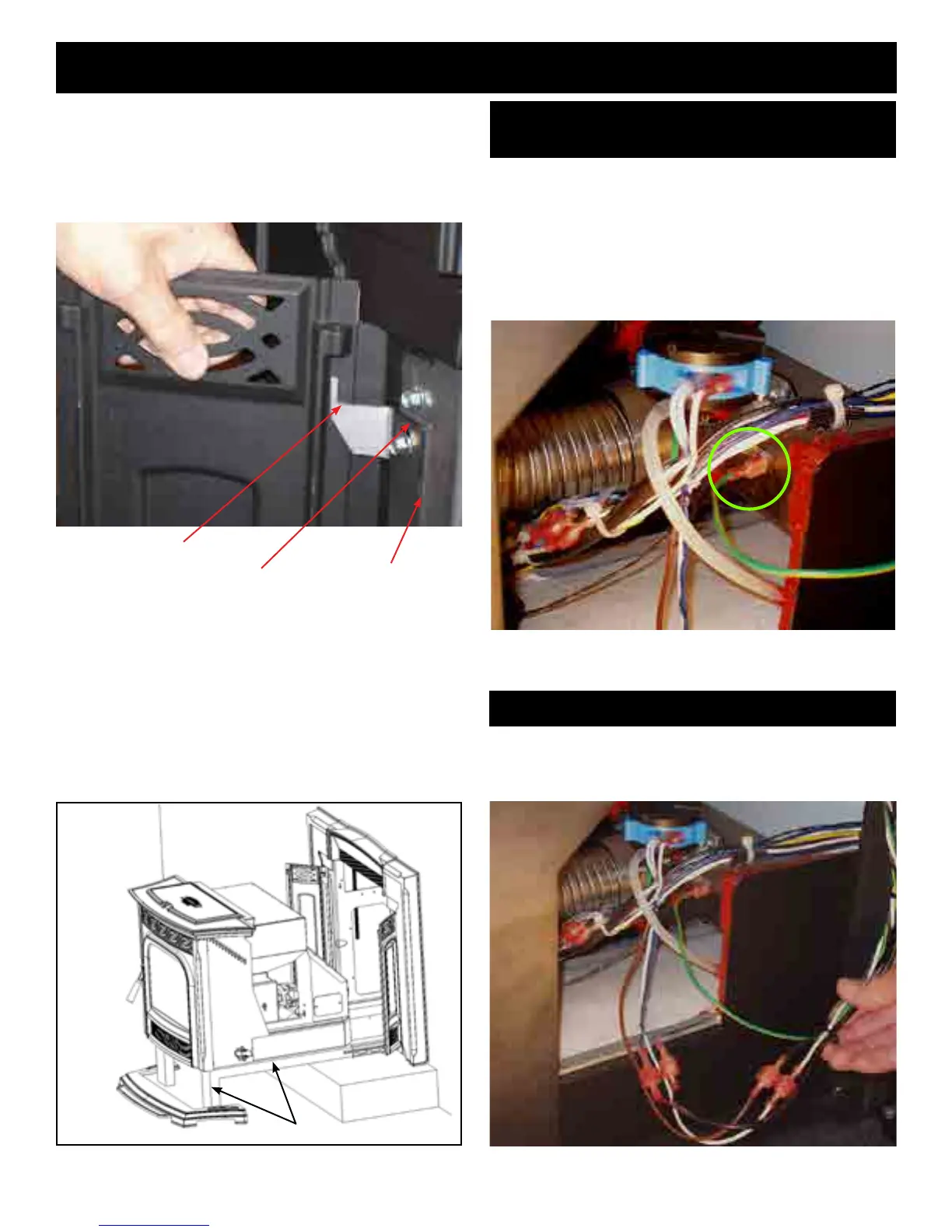
Fig.30
Laseredhingepin
pivotingpoint
Upanddownclearance
adjustmentslots.
Castsidepanel
hinge
Fig.31
2x4
Connecting the ground from the wing to the
stove body