16
3-90-00674R28_12/13
Installation
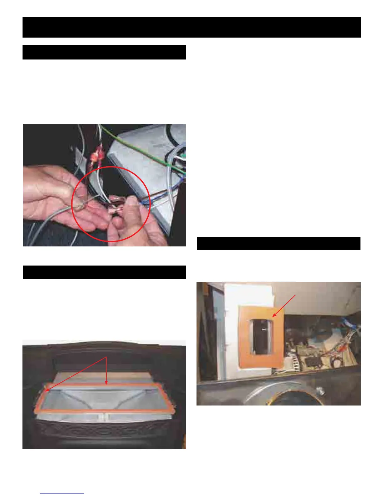
• Connectingtheroomsensortothebluetwistedwiresfrom
thecontrolboard:
• (2)3/16inchmaleterminalsareprovidedfortheendsof
theroomsensorwires.
• Theywill mate with the female terminals on the blue
twistedwires.
• Theseconnectionsare“notpolarityspecic.”
• Inspectthesiliconespongehoppertotopsealgasket.
• Lookfortearsorareaswherethegasketmaynotseal
properlytothebottomofthecasttop.Thisonlyneedsto
bedonewhenthetopisremoved.ThisisNOTnecessary
ifthecasttopisnotremoved.(Notpartofanymonthly,
semi-annualorannualmaintenance.)
Fig.34
Everytimetheunitispulledoutofthemountingframe,the
orangehightemperaturedockinggasketshouldbeinspected.
Checkfortearsorsignsthatthegasketisnotsealingproperly.
19. Inspectthesiliconespongegasketonthetopedgeof
thehopper.
• Ifitisokay,putthecasttop/hopperlidassembly(seeFig.
35)intoplaceoverthehopper.
• Makesurethehopperlidisopentoinstallthetop,then
closeittokeepfromgettingpinchedincasethelidfalls
unexpectedly.
• Insert the (4) 1/4-20 x 1/2 ange head bolts into the
mountingholebutdonottightenthem.Seepage9,g.
12.
20. "Test"theunitwiththestovebodypulledout.Thiswill
allowyoutoseethemotorsinoperation.
• Turnthecontroltothe"OFF"position.
• Plugtheunitintoa120VAC,60Hzoutlet.
• Turnthecontrolto"test".Allofthemotorsshouldoperate
atfullvoltagefor60seconds.
Note:Thedoormustbeclosedforthefeedmotortooperate.
• Withthe"Test"completed,turnthefeedadjusteroffof
test,andunplugtheunit.
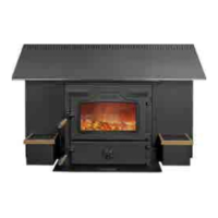
21. Inspecttheuedockinggasket.SeeFig.36.
18. Installthefrontdoor.Checkthelatchandgasketing.
Connecting the Room Sensor
Hopper Seal
Fig.35
Hoppersealgasket(grayororange)
Docking Gasket
Fig.36
DockingGasket