14
3-90-00674R28_12/13
Installation
Therearethreedifferentuepipestubsavailable.
1. Theunitcomesstandardwiththelargest,forusewith4”
stainlesssteelexpipe.
2. Part#1-00-674040isforusewith4”PLventstarterpipe.
3. Part#1-00-674039isforusewith3”PLventstarterpipe
andalsoforusewith3”aluminumexductforoutsideair
connections.
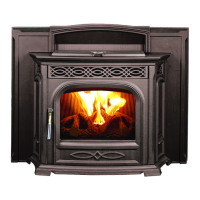
Theuestubassemblybaseisaroundplatewhichallowsit
toswiveltoallowtheuepipetoexitthemountingframein
otherpositionsratherthanstraightup.Seeg.28.
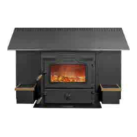
14. Installtheuepipeinsulationwrap.SeeFig.27.This
ceramicinsulationisprecuttoformaroundtheuepipe
stub,toreduceheattransferintotheareaaroundtherear
ofthehopperandmotorarea.This insulation must be
installed in all congurations, even if a rear discharge
is used. SeeFig.29.
Fig.28
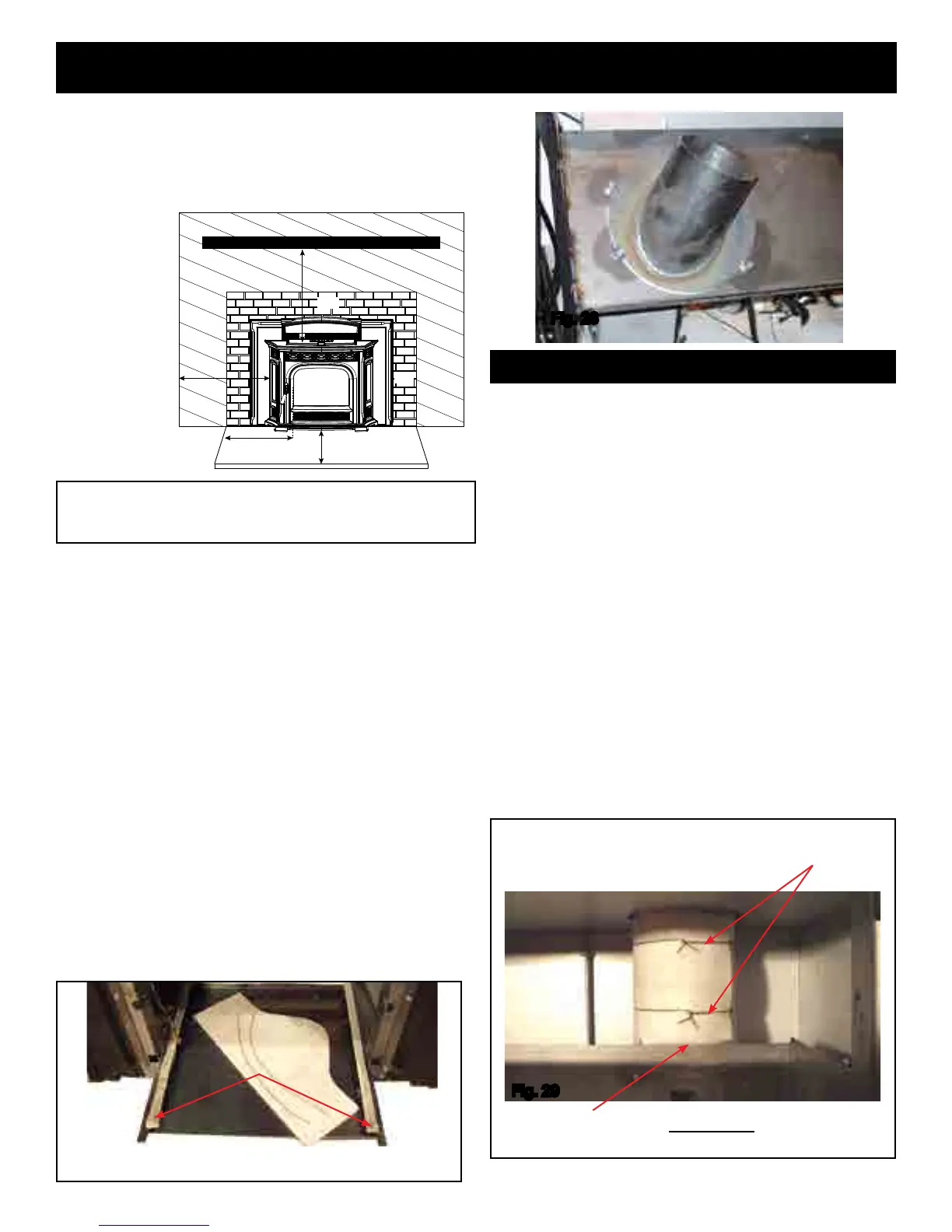
A=tosidewall
B=to12"mantel
C=to3/4"trim
D=to3/4"trim
E=oorprotection
Fig.27
Ash lip
mounting
rails
Pre-cutceramicinsulationand(2)piecesoftiewire.
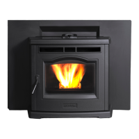
Twisted tie wire
Withlargeruepipesthisbottomedgeoftheinsulationwill
needtobetrimmedtocompletethewrap.
Thispictureshowsthecompletedinsulation
wrapped around the flue pipe from the
mountingframeupward.
Fig.29
Flue Pipe Stub Assembly
*Floorprotectionmustbeusedfromhearthopeningto6"
(152mm)infrontofdoorglassand6"(152mm)toeachside
ofthestovebodytoprotectcombustiblesfromhotashes.A
minimumsizewillbe16.5"deepby30"wideandbemade
ofanon-combustiblematerialormeetULapproval.
10. Testtthecastashlip(Seeg.25)ontheshellframe
mountingrails.Theashlipshouldslide ontheseside
railswithoutliftingupwardoffoftherailsastheashlipis
slidinward.Asmallclearanceofabout1/16"isanideal
spacebetweenthelegsoftheashlipandthehearth.
Thiscastashlipisadecorativepartthatdoesnotand
shouldnotsupportanyweight.
11. Tightenthe(2)1/2"threadedrodsupagainstthelintel
ofthereplaceopening.Itisalsorecommendedtouse
someformofanchoringscrewsthroughthebottomofthe
shellintothehearth.Thereareupto5holesprovided.
Note:Itisagoodideatochecktheashlipagain.The
framemayhaveshiftedwhenthenalanchoringwas
completed.Seeg.26.
12. Completetheuepiping,andoutsideairpiping,ifused.
Makesurethedamperareaissealed.
WARNING! DO NOT CONNECT THIS UNIT TO ANY AIR
DISTRIBUTION DUCT OR SYSTEM.
13. Ifarearexituecongurationisused,withorwithout
outsideair,makesuretheuepipeterminationclearances
arefollowedasperthemanufacturersrecommendations.
12” (305mm) Mantel
B
A
E
E
C
D
CLEARANCES: A B C D E
From Insert Body: 10” 12” 0”* 6” 6"
(From Glass)
*3/4” trim, zero clearance to cast surround