13
3-90-00674R28_12/13
Installation
7.If the room sensor is used as a return air sensor
ratherthanaroomthermostat/sensor,theblackcable
willnotbeused.Theroomsensoritself(grayorblack
cablewithblackandredwires)willbeconnectedto
thebluetwistedwiresfromthecontrolboard.
Note:Thestovebodymustbeabletoslideoutofthe
shelltothelimitofthepowercordwiresforcleaningand
service.Therefore,iftheroomsensorisconnectedas
areturnairsensor,thewireshouldbeconnectedlong
enoughtoallowthis,butnottoolongthatitwouldget
tangledorpinchedanywhere.
Notice: The male/female connections between the
mountingshellandthestovebodyshouldalwaysbe
maintained.Wirenutortapedsplicesshouldneverbe
used.
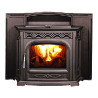
Insertthesensorendofthewirefromtherearofthe
mountingframethroughtheholeasshowning.24.
Wire-tiethesensorendsothatthesensingtipisinthe
middleofthefrontreturnairopening.SeeFig.25.
Wire-tiethesensorwiretotheinsideofthemounting
frame up to the cord grounding location. Follow the
power wiring to where you make the male/female
terminalconnectiontothetwistedbluewires.
Thereare(2)crimp-onconnectorsinthehardwarepack
thatmustbeinstalledontheinternalendsoftheroom
sensorwires.
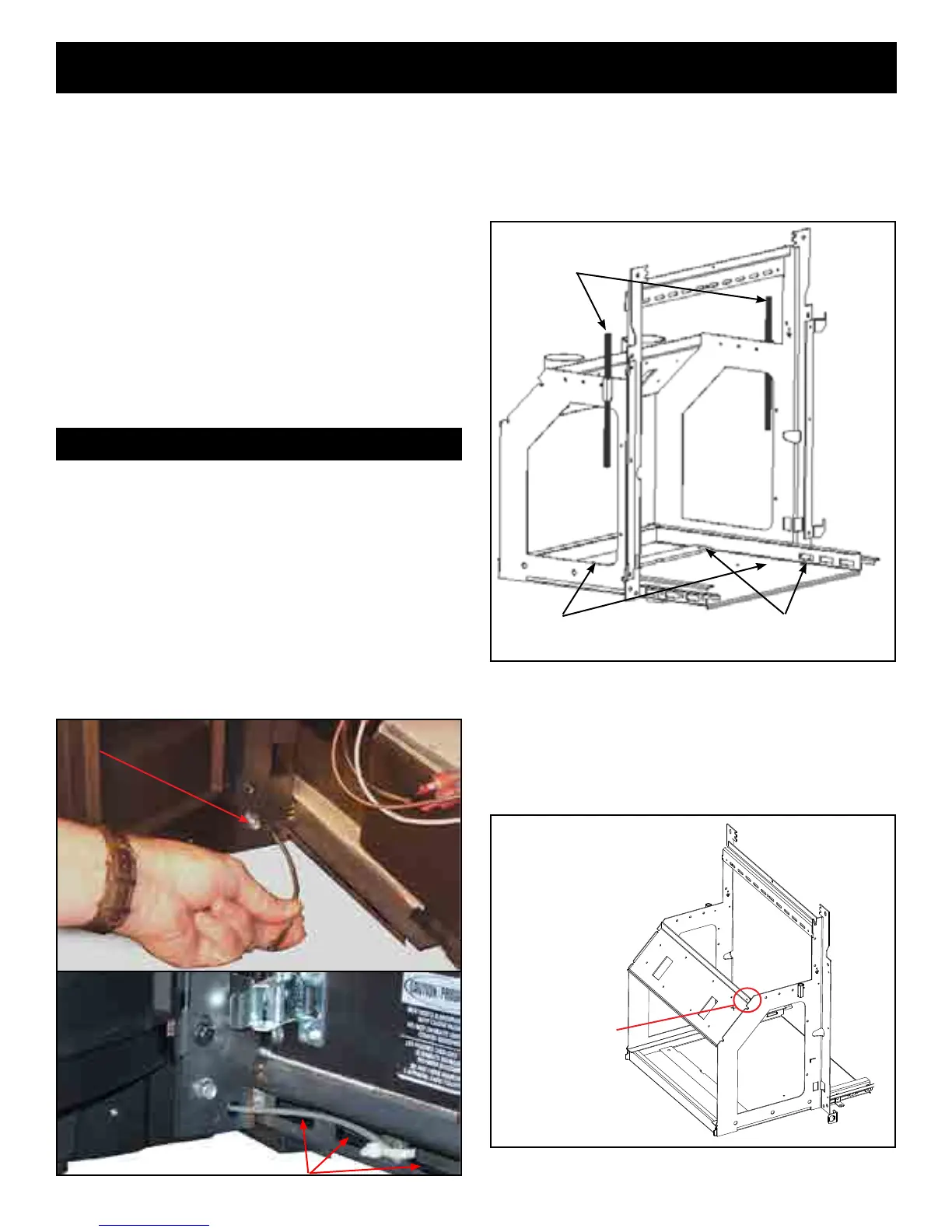
8.Install the (4) 3/8-16x 1" leveling bolts into the
threadedholesinthebottompanofthemounting
shell. The front two leveling bolts may not be
necessary, but the back two will need to be used
tolevelthewingsothatitisushwiththereplace
face.SeeFig.26
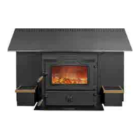
Connecting the room sensor as a return air sensor
9.Installthecompletedframe/surroundassemblyinto
thereboxandlevel/plumbthewingtothereplace
faceusingthelevelingboltsasjacks.
Ifneeded,theinstalledHCS¼-20x1Z5boltcanbe
usedtoadjustthesquarenessofthestovebodyinthe
cage.
3/8x16tapped
levelingboltholes
Fig.26
1/2"threaded
wedgingrods
(5)boltdownholes
SideReturnAirHoles
Fig.25
Fig.24
Adjustbolthere