18
3-90-00674R28_12/13
Always disconnect the power cord before the unit is
pulled from the mounting frame.
Asyoucansee,thecontrolboardiseasilyaccessiblefrom
therearwiththebodypulledoutoftheframe,evenifitis
onlypulledoutseveralinches.
• Alwaysinspectthewiring harnessofthe11pin socket
(large white flat plug where all of the power wires
terminate.)
• Alwaysinspectthewiringharnesswherethewirestransfer
fromthecontroltotherearinsideofthebody.
• Makesuretherearenowornorfrayedareas.
Installation
Log Set Option
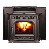
Installthelogbracketwiththetwothumbscrewsprovided.
Centertheloginthereboxopeningwiththebottomfront
edgeoverthethumbscrews.Thelogbranchtipsonlyrest
onthebracketarmsforeasyinstallationandremoval.
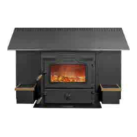
IMPORTANT NOTE: BEFORE CLEANING THE HEAT
EXCHANGERS, THE LOG AND THE LOG BRACKET
MUST BE REMOVED.
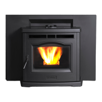
• Do not allow pellets or sawdust to build up on the
hopper lip.
• Inspect the hopper lid gasket for damage. A good
hopper lid seal is very important for proper operation.
Fig.42
Thumb
Screws
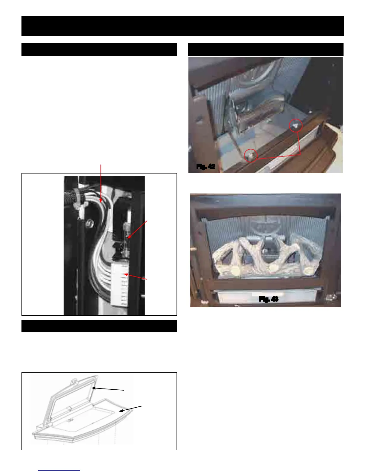
Wiring
6 amp
glass
fuse
Inspect the wiring harness transition area: This is the area
that comes closest to the mounting frame as the unit is slid
in and out of the frame.
11 pin
socket
on rear
of control
board
REMINDERS
Fig. 43
Hopperlidfoam
gaskets
CastTop
Fig.41
Fig.40