pg. 21
Front Panel Components
The following sections list the front panel components on the MU-series controllers. Each component is featured on all
MU-series controllers except where noted.
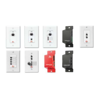
Program Port
The front panel of all models features one USB-C port for connecting the controller to a PC via USB cable.
The Program port uses a standard Type-C-to-Type-A or Type-C-to-Type-C USB cable that supports USB 2.0/1.1 signals to
connect to a PC. When connected, you can use your favorite terminal program to communicate to the MU directly.
FIG. 9 USB-C Program port On MU-1000 (Left), MU-1300 (Center), and MU-2300/3300 (Right)
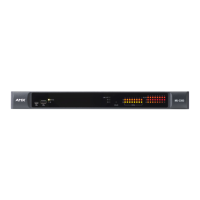
USB Port
The front panel of all models except the MU-1000 features one Type-A USB port use with a mass storage device.
NOTE: This USB port only supports a FAT32 file system.
This USB port (FIG. 10) uses standard USB cabling to connect to any mass storage or peripheral devices.
FIG. 10 USB Type A host port on MU-1300 (Left) and MU-2300 & MU-3300 (Right)
LEDs
This section details the various LEDs on the front panel of the MU-series controllers.
General Status LEDs
The General Status LEDs include the Link/Activity and Status LEDs. These LEDs appear on all models of MU-series
controllers.
• Link/Act - Lights green when the link is up and toggles off when a data packet is sent or received.
• Status - The MU-series features one visible-light tri-color status LED. The following table lists the LED colors and patterns of
the status LED.
ID Button Held (Release for Locate Message broadcast)
ID Button Held (Release for Config reset)
ID Button Held (Release for Factory reset)
Error connecting to built-in ports
Please see ID Pushbutton for detailed ID Button / Reset behavior
 Loading...