20
ZonePRO
TM
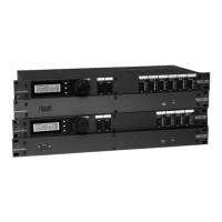
The below diagram shows an example of the DIP switch ID assignments, ZC Input port
connections, and ZC Panel Configuration programming for 12 Zone Controllers.
ZC INPUT
ZC INPUT
(Top ZC Input Port)
ZonePRO Designer
Software Programming
DIP
Switches ZCs
VOLUME
0
1
2
3
4
5
6
7
8
9
10
ZC-1
ZC-3
VOLUME
0
1
2
3
4
5
6
7
8
9
10
ZC-1
ZC-3
VOLUME
0
1
2
3
4
5
6
7
8
9
10
ZC-1
ZC-3
(Bottom ZC Input Port)
ZonePRO Designer
Software Programming
DIP
SwitchesZCs
VOLUME
0
1
2
3
4
5
6
7
8
9
10
ZC-1
ZC-3
VOLUME
0
1
2
3
4
5
6
7
8
9
10
ZC-1
ZC-3
VOLUME
0
1
2
3
4
5
6
7
8
9
10
ZC-1
ZC-3
A
B
C
D
SELECT
A
B
C
D
A
B
C
D
SELECT
A
B
C
D
A
B
C
D
SELECT
A
B
C
D
A
B
C
D
SELECT
A
B
C
D
A
B
C
D
SELECT
A
B
C
D
A
B
C
D
SELECT
A
B
C
D
ID#1
ID#2
ID#3
ID#4
ID#5
ID#6
ID#7
ID#8
ID#9
ID#10
ID#11
ID#12
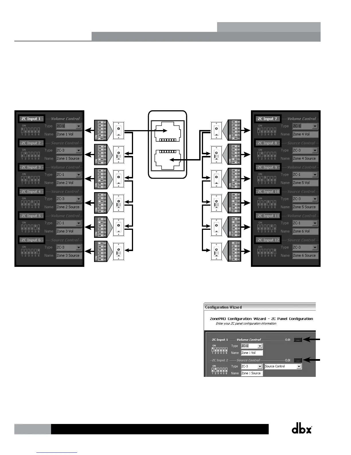
When programming the ZCs on the ZC Panel Configuration page,
you will also notice an Edit button next to each assigned ZC.
You will need to click on the Edit button for each assigned ZC
to further define how each ZC will function. For example, this
is where you would set a volume controller’s range constraints
(defining how much gain or attenuation the end user is
allowed to apply when turning the ZC volume up or down) or
assign which input sources will be selected when programming
a source selection controller.
Zone Controllers
Section 4