Date printed: 24.01.12
87
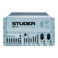
D21m System
S2
5678 1234
ON
Default Setting:
S1
5678 1234
ON
Default Setting:
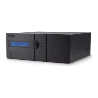
DIP Switches S1 DIP switch for parameter/routing setting:
No. Setting Default Setting
1 ON: Bypass rear OFF
2 ON: Bypass front OFF
3 ON: Front control OFF
4 ON: HD card as host OFF
5 not used OFF
6
ON: +24 VDC supply switched to pins 1 and 2 of all RJ45 con-
nectors simultaneously (used for supplying OnAir 3000 desk
modules)
OFF
7
* ON: HD card connect
ON
8
* ON: HD card connect
ON
* Must be set to identical positions
S2 DIP switch for RS422 pinout selection of the HOST/8-15 connector:
1 2 3 4 5 6 7 8 Setting
OFF OFF OFF OFF ON ON ON ON RS422 Controller pinout
ON ON ON ON OFF OFF OFF OFF
RS422 Device pinout (factory
default)
NO OTHER SETTINGS ALLOWED!
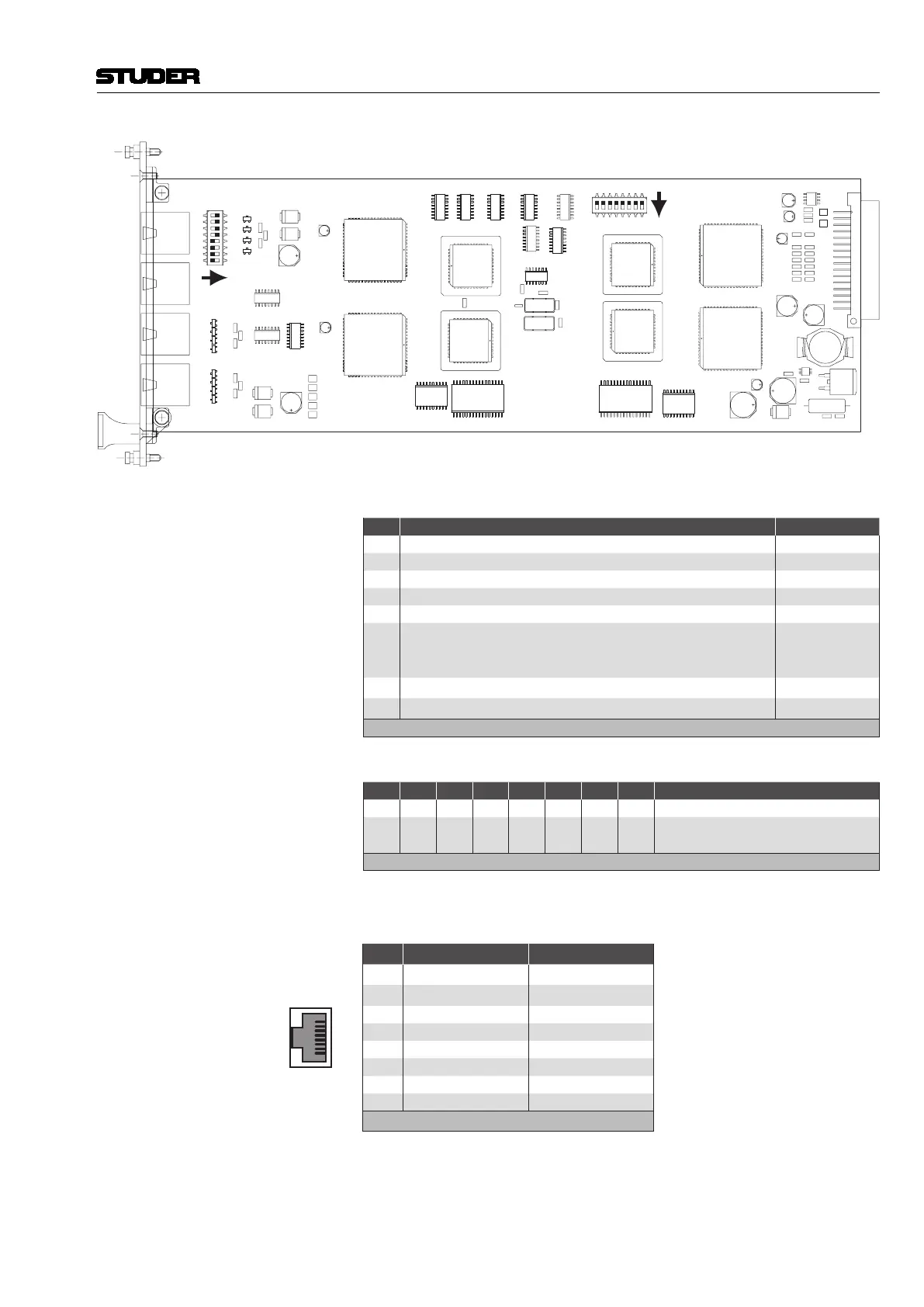
Connector Pin Assignment HOST (8pin RJ45)
1
8
Socket View
Pin RS422 Controller RS422 Device
1
* n.c. * n.c.
2
* n.c. * n.c.
3 TxD + RxD +
4 RxD + TxD +
5 RxD – TxD –
6 TxD – RxD –
7 GND GND
8 GND GND
* or +24 VDC if SW 6 of DIP switch 1 is set to ON
Note The three lower connectors 16-23, 24-31, and 32-39 are always wired in
‘controller’ mode and cannot be switched to ‘device’ mode.
 Loading...