Date printed: 24.01.12
88
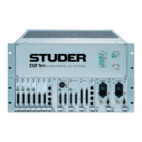
D21m System
6.7 Power Supply and Miscellaneous
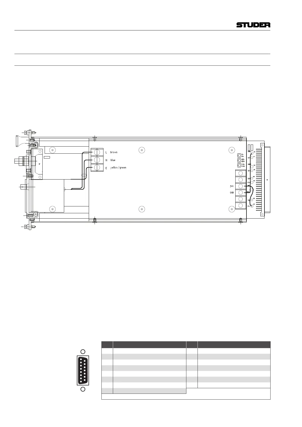
6.7.1 Primary Power Supply A949.0404 (earlier version: A949.0403)
The D21m I/O frame may be equipped with either one or, for redundancy
purposes, with two primary power supply units.
The module used is a primary switching AC/DC converter with an input
voltage range of 90-264 VAC/50-60 Hz, automatic power factor correction
and a standard IEC mains inlet. Output is 24 VDC/max. 8.5 A. It contains no
adjustable elements; if the internal primary fuse should fail, the unit must be
returned to the factory for repair.
The primary power supply unit(s) is/are plugged directly into the PSII PCB
A949.0402, where all required voltages for the frame are generated.
FAN/STATUS Connector This front-panel connector (15-pin D-type f for A949.0404; 9-pin D-type f
for A949.0403) is used to output an electrically isolated status signal when
the primary power supply (or one of them) should fail. The contacts of a relay
located on the LED/PSII PCB are available on this connector, as well as a
+24 VDC supply and ground. The relay is energized as long as all supply
voltages are ok, pins 4 and 6 (or pins 1 and 2 on A949.0403) are connected
then. In case of failure of any of the frame’s supply voltages, pins 6 and 8 (or
pins 2 and 3 on A949.0403) are connected. The connector in addition allows
supplying a fan unit (A949.0597); for the 15-pin connector on the current
version A949.0404 a 1:1 m/f cable (C089.201167)is used.
Please note that only the connector of the right-hand primary PSU can be
used for the status and supply signals, even if two primary power supply units
are installed in the D21m I/O frame.
Pin Assignment FAN/STATUS (15pin D-type, female, UNC 4-40 thread) on A949.0404:
1
8
15
9
Solder/Crimp View
(or Socket View)
Pin Signal Pin Signal
1 +24 VDC (fan supply, 650 mA max.) 9 GND
2 reserved - do not connect! 10 n.c.
3 GND 11 n.c.
4 * Relay NO (normally ope n) 12 reserved - do not connect!
5 ** Fan supply OK (active low) 13 ** Fan in (active low)
6 * Relay COMMON 14 reserved - do not connect!
7 GND 15 n.c.
8 Relay NC (normally closed)
* Connected if everything is ok ** Status signals, foreseen for fan supervision
 Loading...