Date printed: 24.01.12
25
D21m System
RA1
RA2
RA3
RA4
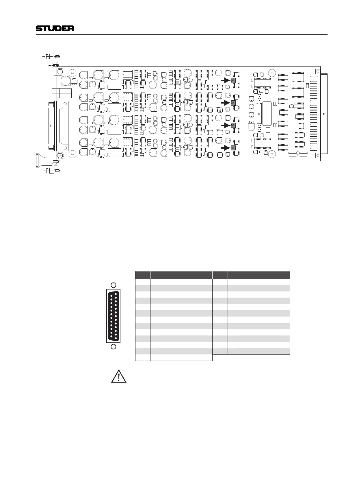
RA1...4: Factory Setting (Level Fine-Adjustment)
LEDs PHANTOM 1-4 For each channel a yellow LED indicates that pantom power is on.
SIGNAL 1-4 For each channel a green LED indicates whether input signal is present; its
brightness is a rough indication of the signal level.
Alignment RA1-4 Please note that the level fine-adjust trimmer potentiometers are factory-set.
They need to be adjusted only after having repaired the card.
Select 15 dBu input sensitivity. Feed an analog signal with a level of +6 dBu to
one of the analog inputs. Measure the digital output level either on the MADI
output or, after routing through the core, on one of the AES/EBU outputs.
Adjust the level with the corresponding trimmer potentiometer to –9 dB
FS
.
Connector Pin Assignment 4× BALANCED MIC IN/SPLIT OUT (25pin D-type, fem., UNC 4-40 thread)
1
Solder/Crimp View
(or Socket View)
13
25
14
Pin Signal Pin Signal
1 CH 4 split out + 14 CH 4 split out –
2 CH 4 split out GND 15 CH 3 split out +
3 CH 3 split out – 16 CH 3 split out GND
4 CH 2 split out + 17 CH 2 split out –
5 CH 2 split out GND 18 CH 1 split out +
6 CH 1 split out – 19 CH 1 split out GND
7 CH 4 in + 20 CH 4 in –
8 CH 4 in GND 21 CH 3 in +
9 CH 3 in – 22 CH 3 in GND
10 CH 2 in + 23 CH 2 in –
11 CH 2 in GND 24 CH 1 in +
12 CH 1 in – 25 CH 1 in GND
13 n.c.
Important! If wired correctly, the microphones are isolated from the D21m chassis. The
circuit within the microphone takes its supply from pins 2 and 3 (+ and –) for
the positive, and from pin 1 (GND) for the negative reference. If a patch bay
is implemented, GND (pin 1 on XLR connector) of each microphone input
must be connected to its corresponding GND pin, but not to the chassis. If
the chassis is used as negative reference for a microphone instead of GND,
the GND net of the D21m is pulled towards –48 V. This causes the HD link
receivers not to work correctly or to be damaged, depending on the type and
the number of microphones connected.
As a workaround, GND and chassis may be connected within the D21m frame.
If currents flow between the chassis nets of multiple devices, the analog sig-
nals can be degraded in quality (e.g. perceivable as hum).