Date printed: 24.01.12
27
D21m System
*
§
§§
**
*
§
§§
**
*
§
§§
**
*
§
§§
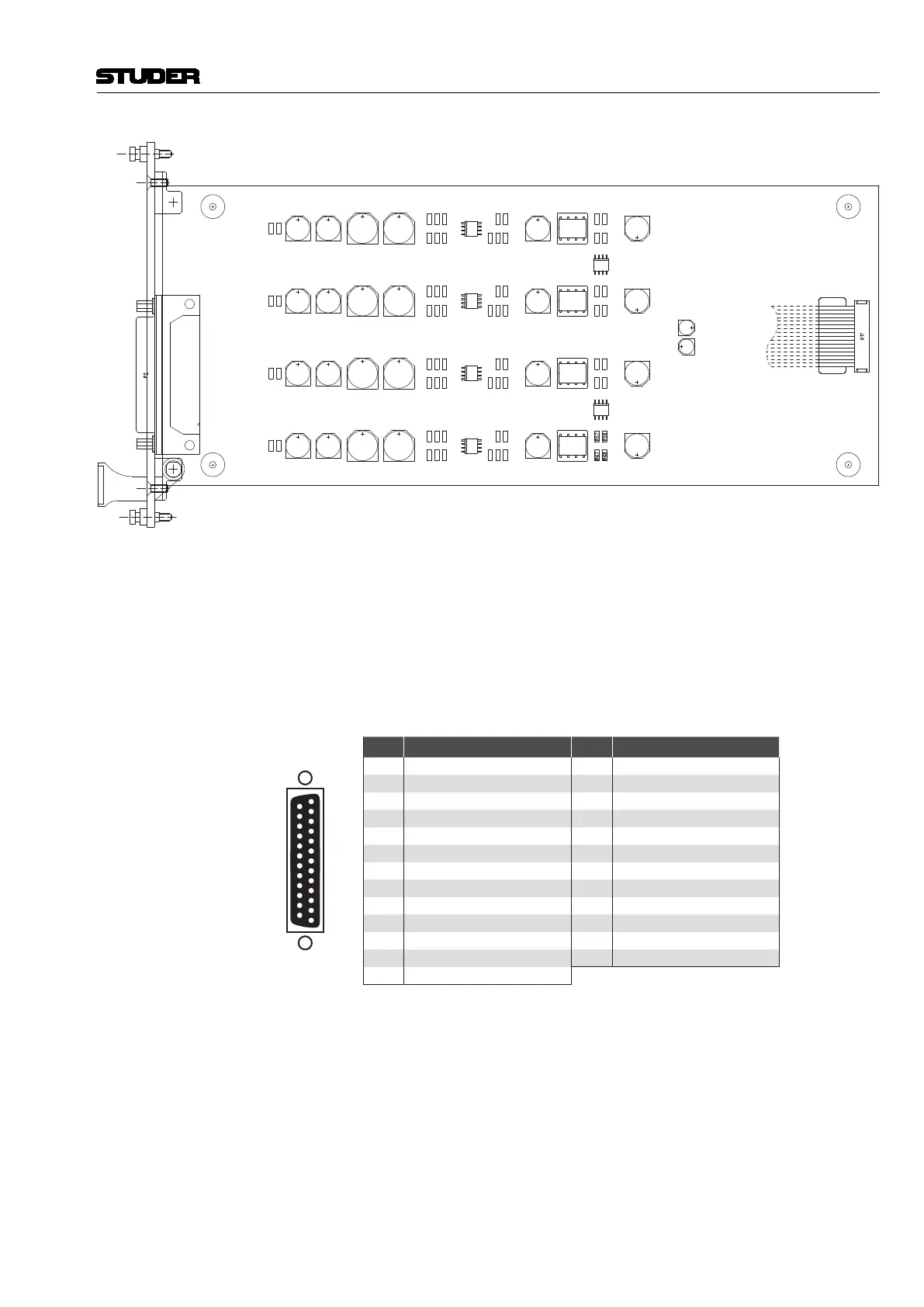
Important:
Do NOT connect * and **
or § and §§ simultaneously
* = Connect for Return Level –9 dB
** = Connect for Return Level +9 dB
§ = Connect for Send Level +9 dB
§§ = Connect for Send Level –9 dB
Solder Pads:
**
Ch 1
Ch 2
Ch 3
Ch 4
Solder Pads Nominal send/return levels are +15 dBu for full scale modulation. These levels
may be boosted or cut by 9 dB (i.e., set to +6 dBu or +24 dBu) individually
per channel and for send and return, refer to the illustration above.
Please note that the corresponding +9 dB and –9 dB solder pads must not be
connected simultaneously.
Connector Pin Assignment 4× BALANCED LINE IN AND OUT (25pin D-type, fem., UNC 4-40 thread)
1
Solder/Crimp View
(or Socket View)
13
25
14
Pin Signal Pin Signal
1 CH 4 out + 14 CH 4 out –
2 CH 4 out GND 15 CH 3 out +
3 CH 3 out – 16 CH 3 out GND
4 CH 2 out + 17 CH 2 out –
5 CH 2 out GND 18 CH 1 out +
6 CH 1 out – 19 CH 1 out GND
7 CH 4 in + 20 CH 4 in –
8 CH 4 in GND 21 CH 3 in +
9 CH 3 in – 22 CH 3 in GND
10 CH 2 in + 23 CH 2 in –
11 CH 2 in GND 24 CH 1 in +
12 CH 1 in – 25 CH 1 in GND
13 n.c.