Date printed: 24.01.12
29
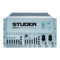
D21m System
RA1
RA2
RA3
RA4
RA1...4: Factory Setting (Level Fine-Adjustment)
LEDs PHANTOM 1-4 For each channel a yellow LED indicates that pantom power is on.
SIGNAL 1-4 For each channel a green LED indicates whether input signal is present; its
brightness is a rough indication of the signal level.
Alignment RA1-4 Please note that the level fine-adjust trimmer potentiometers are factory-set.
They need to be adjusted only after having repaired the card.
Select 15 dBu input sensitivity. Feed an analog signal with a level of +6 dBu to
one of the analog inputs. Measure the digital output level either on the MADI
output or, after routing through the core, on one of the AES/EBU outputs.
Adjust the level with the corresponding trimmer potentiometer to –9 dB
FS
.
Connector Pin Assignment 4× BALANCED MIC IN/SPLIT OUT (25pin D-type, fem., UNC 4-40 thread)
1
Solder/Crimp View
(or Socket View)
13
25
14
Pin Signal Pin Signal
1 CH 4 split out + 14 CH 4 split out –
2 CH 4 split out GND 15 CH 3 split out +
3 CH 3 split out – 16 CH 3 split out GND
4 CH 2 split out + 17 CH 2 split out –
5 CH 2 split out GND 18 CH 1 split out +
6 CH 1 split out – 19 CH 1 split out GND
7 CH 4 in + 20 CH 4 in –
8 CH 4 in GND 21 CH 3 in +
9 CH 3 in – 22 CH 3 in GND
10 CH 2 in + 23 CH 2 in –
11 CH 2 in GND 24 CH 1 in +
12 CH 1 in – 25 CH 1 in GND
13 n.c.