Chipper/Shredder
R
5. Mount drive pulley on drum shaft. Align
pulleys and tighten to 17 ft-lb. Mount belt
on unit routing idler in center of belt.
Install belt shield using 5/16” bolts and at
washers.
6. Mount lower directional spout to blower
using 5/16” bolts and at washers.
7. Mount upper directional spout to lower
using 5/16” x 3/4” bolts, 5/16” lock nuts
and bearings. Make sure that 1/4” washer
is placed between bearing and mount tab.
8. Mount crank assembly to mount tab using
2 3/8” x 1” carriage bolts and 3/8” nylock
nuts. Place 2 3/8” at washers under each
bolt location to shim up crank assy.
NOTE: This may vary due to required
clearance for crank.
9. Mount deector spout to upper spout
using 2 5/16” x 34” truss head bolts. A
5/16” washer is used for a spacer
between deector and spout.
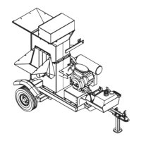
Discharge Grates
• The factory-installed standard dis-
charge grate has 1½” diameter holes.
• Installing a discharge grate with small-
er diameter holes can increase ne-
ness of the shredded material.
• Discharge grates with ½” and ¾” diam-
eter holes are available for the Chip
per/Shredder.
• A discharge grate with parallel bars is
available for shredding leaves or green
material.
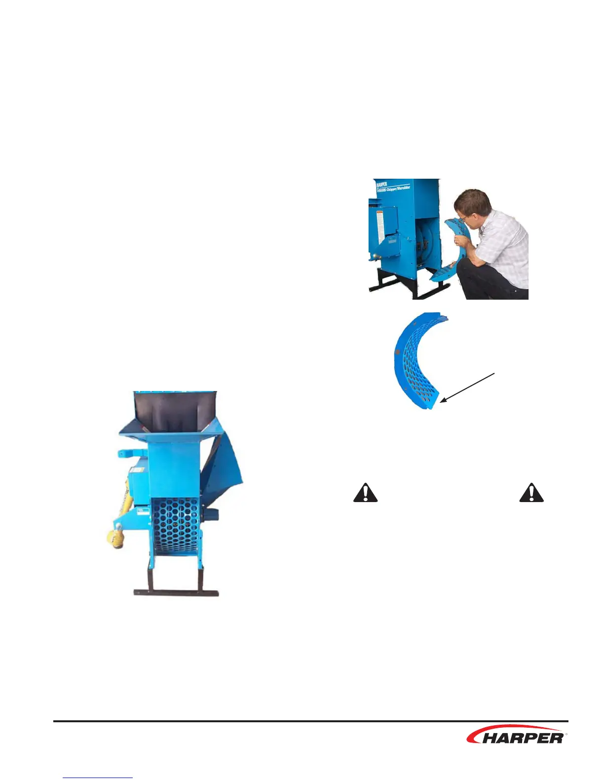
To change discharge grates:
1. Remove the rear door hinge pin and
remove the rear safety door.
2. Remove the 6- 3/8” x 1” bolts holding the
grate in place. Remove the grate.
3. Install new grate. Make sure to install the
rounded edge of the grate to the bottom.
4. Reinstall bolts and rear safety door.
SAFETY WARNING!
• The cutting rotor is heavy and will
continue to turn even though the
operator has shut off the power
source. Do not attempt to service or
inspect the machine until you see
that the shafts have stopped turn-
ing and that there is no noise com-
ing from the machine.
• Never operate Chipper/Shredder
without ALL GUARDS in place.
Install this
end down
11