DA-DHR/DH/DSR/DS/HR/H6802+ Installation and Operation Manual 5
Chapter 1: Introduction
Preliminary—Contents are proprietary and confidential. Do not photocopy or distribute.
Module Descriptions
Front Module
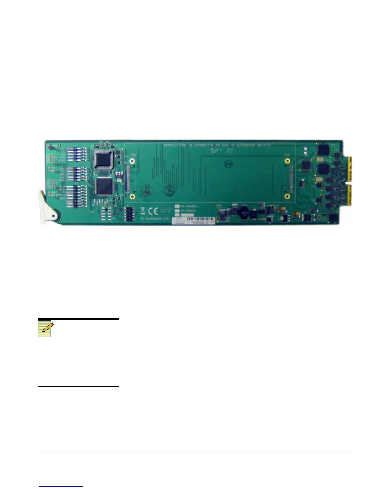
Figure 1-1 is a generic top-front view of a typical front module. See
Figure 3-1 on page 20 for jumper locations; see Figure 3-2 on page 27
and Figure 3-3 on page 28 for LED locations.
Figure 1-1. Typical Front Module
Back Modules
DA-DHR/DH/DSR/DS/HR/H6802+ modules can be installed with
double-width back connectors in FR6802+X(F) and FR6802+DM
frames. These modules cannot be installed in 6800 / 7000 series frames.
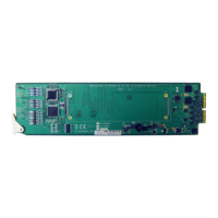
FR6802+X(F) Frame Back Module
Figure 1-2 shows the double-width back connector module used by the
DA-DHR/DH/DSR/DS/HR/H6802+ when installed in an
FR6802+X(F) frame.
Note
Distribution amplifiers with
unused inputs should have the
input terminated. Not doing so
may cause erroneous readings of
a valid input signal that can be
induced from adjacent slots.