Do you have a question about the Harris DA-DHR6802+ and is the answer not in the manual?
Introduces the topics covered in Chapter 1, including features and descriptions.
Details the features and configurations of the 6800+ series distribution amplifiers.
Lists the key capabilities and configurable options of the DA-DHR6802+ module.
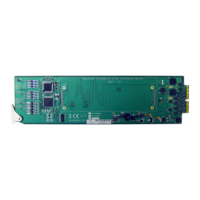
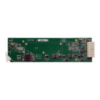
Describes the front and back modules used with the 6800+ series distribution amplifiers.
Illustrates the signal path and components within the 6800+ distribution amplifier module.
Describes the process of installing DA-DHR/DH/DSR/DS/HR/H6802+ modules.
Details the maximum allowable power ratings for 6800+ frames and module compatibility.
Provides instructions on checking equipment for damage and preparing for installation.
Lists the components expected for Dual 1x4 Distribution Amplifier Modules.
Explains how to configure module settings using jumpers.
Details how to set the J3 jumper for channel configuration and control mode.
Explains how to set J4/J5 jumpers for output slew rate control.
Specifies compatible frames and back connectors for 6800+ modules.
Notes that no specialized installation procedures are required for the modules.
States that no specialized removal procedures are needed for the modules.
Guides on connecting the module to appropriate inputs and outputs after installation.
Describes how to operate the distribution amplifier modules using local controls.
Provides information on parameter changes and their effect on the module.
Explains the function and usage of various jumpers on the module.
Details how to use J1/J2 jumpers for local control reclock settings.
Explains the function of the J3 jumper for remote control, backup, and channel configuration.
Describes how to use J4/J5 jumpers for setting output slew rate control.
Explains adjustable and read-only parameters available on the modules.
Details numerical and selectable parameters that can be changed via controls.
Describes parameters indicated by [RO] that provide status information.
Guides on setting parameters using local controls, focusing on reclocking modes.
Describes parameters accessible remotely via CCS control software.
Explains how to change module parameters locally or remotely.
States that default parameter settings cannot be recalled.
Guides on viewing the module's software version using Pilot.
Guides on viewing the module's hardware revision using Pilot.
Explains the function of the Module Status Indicator LED.
Lists and describes the function of various LEDs on the 6800+ modules.
Explains that alarms are logged and monitored via software control applications.
Provides detailed specifications for the input signals of the distribution amplifiers.
Provides detailed specifications for the output signals of the distribution amplifiers.
Details performance specifications such as jitter and propagation delay.
States the module's power consumption is less than 6 W.
Lists the performance and operating temperature ranges for the modules.
Indicates the approximate start-up time for the module.