DA-DHR/DH/DSR/DS/HR/H6802+ Installation and Operation Manual 21
Chapter 3: Operation
Preliminary—Contents are proprietary and confidential. Do not photocopy or distribute.
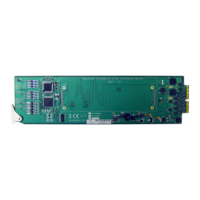
J1/J2 Jumpers
You can use the J1 (for channel 1 control) or J2
1
(for channel 2 control)
jumper to select local control reclock setting.
Figure 3-1 on page 20 illustrates the location of these jumpers. See
Figure 2-1 on page 14 for a close-up view of the J1 /J2 jumper set.
For local control, the J1 /J2 jumpers are used to determine reclocking
mode. See “Setting Locally Controlled Parameters” on page 23 for
more information.
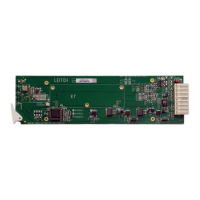
J3 Jumpers
Figure 3-1 on page 20 illustrates the location of this jumper. See
Figure 2-2 on page 15 for a close-up view of the J3 jumper set.
You can use the J3 jumper set to select the following items:
• Remote control: When the jumper is set to the “remote” position,
the reclocker setting is handled by + Pilot Lite only. You may select
the three setting modes (automatic, manual, and bypass) remotely
via + Pilot Lite.
• Backup_EN: When the BACKUP_EN switch is installed, the
module automatically selects input 2 to be an input source when
input 1 has lost its input signal. When the input signal returns, the
outputs will return to input 1 as the distribution amplifier is
configured (as 1×8 mode for DA-DHR6802+, DA-H6802+).
• Channel configuration: This switch allows you to configure the
module to operate as a 1×8 or as a dual 1×4 for DA-DHR6802+,
DA-H6802+.
J4/J5 Jumpers
Figure 3-1 on page 20 illustrates the location of this jumper. See
Figure 2-2 on page 15 for a close-up view of the J4/J5 jumper set. See
Table 2-4 on page 17 for automatic and manual slew rate settings.
You can use the J4/J5 jumper set to set the output slew rate control. You
can choose from
• Automatic slew rate: for the reclockable input signal in
DA-DHR6802+ and DA-HR6802+
1
Jumper J2 is not operational in DA-HR/H6802+ modules.