Installing the System Card and Battery
7
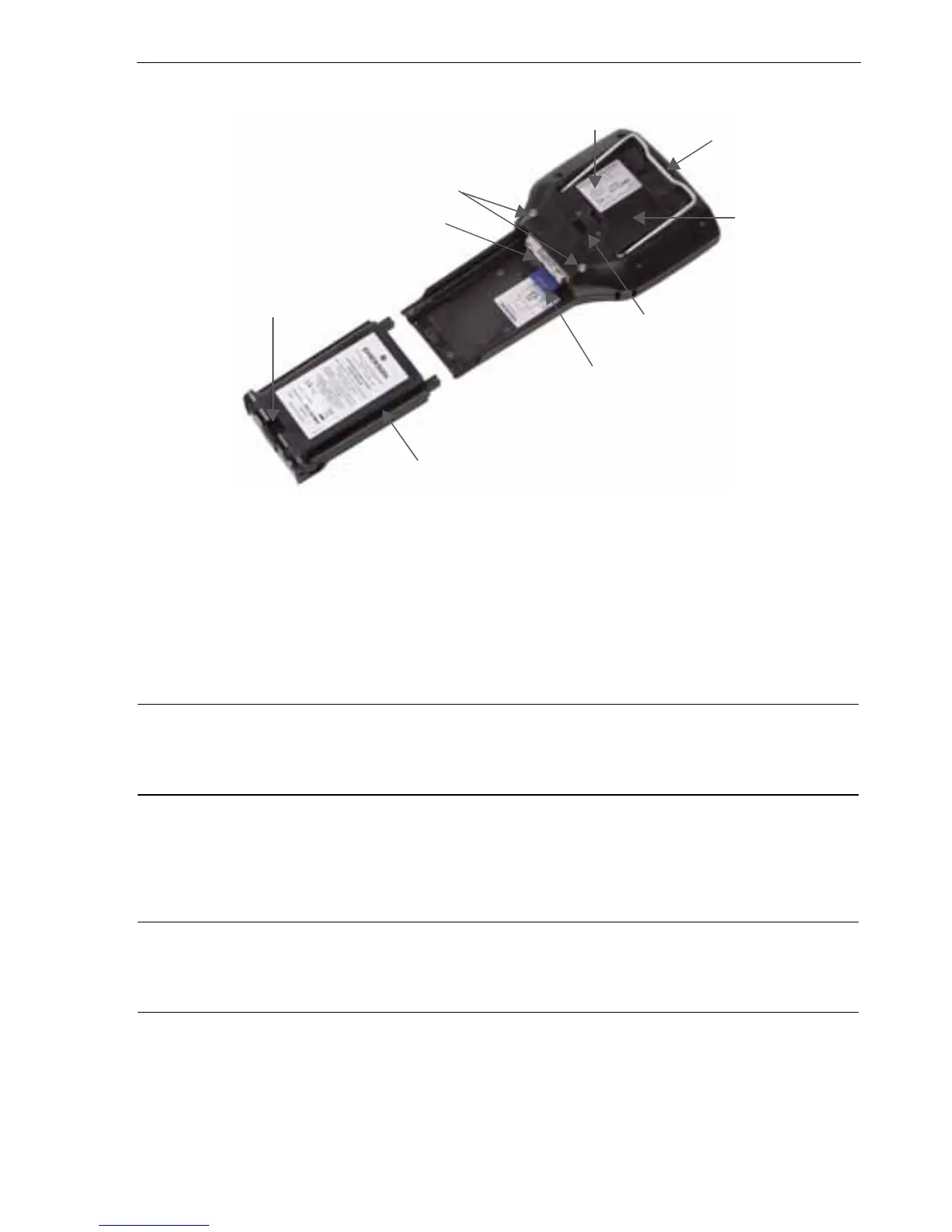
Figure 2. Back of the 475 Field Communicator
INSTALLING THE SYSTEM CARD AND BATTERY
1. Remove the protective rubber boot, if attached.
2. Place the 475 Field Communicator face down on a level, secure surface.
3. With the battery removed, slide the Secure Digital System Card (labeled System
Card), with the card contacts facing up, into the System Card socket until it clicks.
See Figure 2. The System Card socket is spring-loaded.
CAUTION
The System Card must be supplied by the 475 Field Communicator manufacturer.
Failure to comply will void the IS approval.
4. With the 475 Field Communicator still face down, ensure the two battery retaining
screws are loose.
5. Align the battery with the sides of 475 Field Communicator, and carefully slide the
battery forward until it is secure.
CAUTION
The connector pins may be damaged if the battery and 475 Field Communicator are
improperly aligned.
6. Carefully hand tighten the two battery retaining screws. (Do not over tighten, 0.5Nm
maximum torque load.) The tops of the screws should be nearly flush with the 475
Field Communicator.
Battery Retaining Screws
Li-Ion Battery
Connector Pins
System Card in the
System Card Socket
Main Unit Label
Strap Attachment
Strap Attachment
IS Label
Location
(KL Option)
Stand