11 – English
KNOW YOUR COMPOUND MITER SAW
See Figures 1 - 2.
Thesafeuseofthisproductrequiresanunderstandingof
theinformationonthetoolandinthisoperator’smanualas
wellasaknowledgeoftheprojectyouareattempting.Before
useofthisproduct, familiarizeyourself withalloperating
featuresandsafetyrules.
7-1/4 IN. BLADE
A7-1/4in.bladeisincludedwiththecompoundmitersaw.
Itwillcutmaterialsupto1-1/2in.thickor4-1/4in.wide,
dependingupontheangleatwhichthecutisbeingmade.
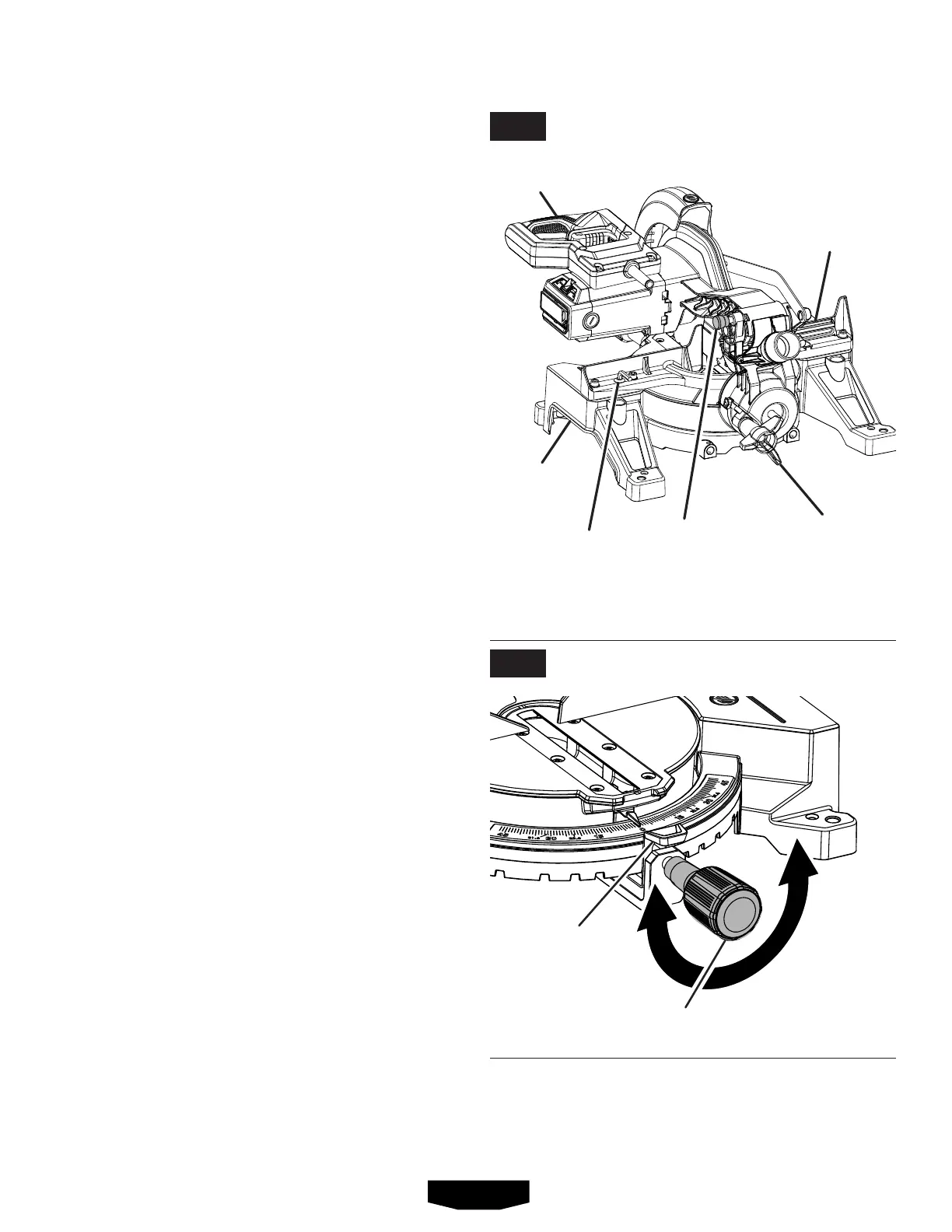
BEVEL LOCK KNOB
See Figure 3.
Thebevellockknobsecurelylocksyourcompoundmiter
sawatdesired bevel angles.Apositivestop adjustment
screwhas been providedoneachside of the saw arm.
Theseadjustmentscrewsareformakingfineadjustments
at0°and45°.
BLADE WRENCH STORAGE
Abladewrench is packedwiththesaw. One end ofthe
wrenchisaPhillipsscrewdriverandtheotherendisahex
key.Usethehexkeyendwheninstallingorremovingblade
andthePhillipsendwhenremovingorlooseningscrews.
Astorageareaforthebladewrenchislocatedontheback
ofthemiterfence.
HANDLE AREA
See Figure 3.
Forconveniencewhencarryingortransportingthemitersaw
fromoneplacetoanother,handleareashavebeenprovided
oneithersideofthesawbase.Totransport,turnoffand
unplugthesaw,securelytightentheslidelockknob,then
lowerthesawarmandlockitinthedownposition.Lock
sawarmbypushingthelockpinin.
NOTE:DONOTperformanycuttingoperationwiththesaw
inthelockedposition.
MITER FENCE
Themiterfenceon the compoundmitersaw has been
providedto hold yourworkpiecesecurelyagainstwhen
makingallcuts.
MITER LOCK KNOB
See Figure 4.
Themiterlockknobsecurelylocksthesawatdesiredmiter
angles.Turnthemiterlockknobclockwisetolockthesaw
inplace.Toreleasethesaw,turnthethemiterlockknob
counterclockwiseanddepressthedetentreleasebutton.
SAW ARM LOCKED IN DOWN POSITION
LOCK PIN
TO
LOOSEN
MITER
LOCK KNOB
TO
TIGHTEN
BEVEL
LOCK KNOB
“D”
HANDLE
PARTIAL
SLIDING
FENCE
DETENT
RELEASE
BUTTON
BLADE
WRENCH
HANDLE
AREA
FEATURES
FIG. 3
FIG. 4