12 – English
PARTIAL SLIDING FENCE
Thepartialslidingfenceonyourcompoundmitersawhas
beenprovidedtohelpsecuretheworkpiecewhenmaking
straightcuts.
Theslidingfeaturemakesiteasytoadjustthepositionof
thepartialfence.Loosenthefencescrewbeforeattempt-
ingtoslidethepartialfence.Oncethedesiredpositionis
determined,tightenthefencescrewtosecure.
POSITIVE STOPS ON MITER TABLE
Positivestopshavebeenprovidedat0°,15°,22.5°,31.6°,
and45°onboththeleftandrightsideofthemitertable.
SELF-RETRACTING LOWER BLADE GUARD
The lowerbladeguard is made of shock-resistant,see-
throughplasticthatprovidesprotectionfromeachsideof
theblade.Itretractsovertheupperbladeguardasthesaw
isloweredintotheworkpiece.
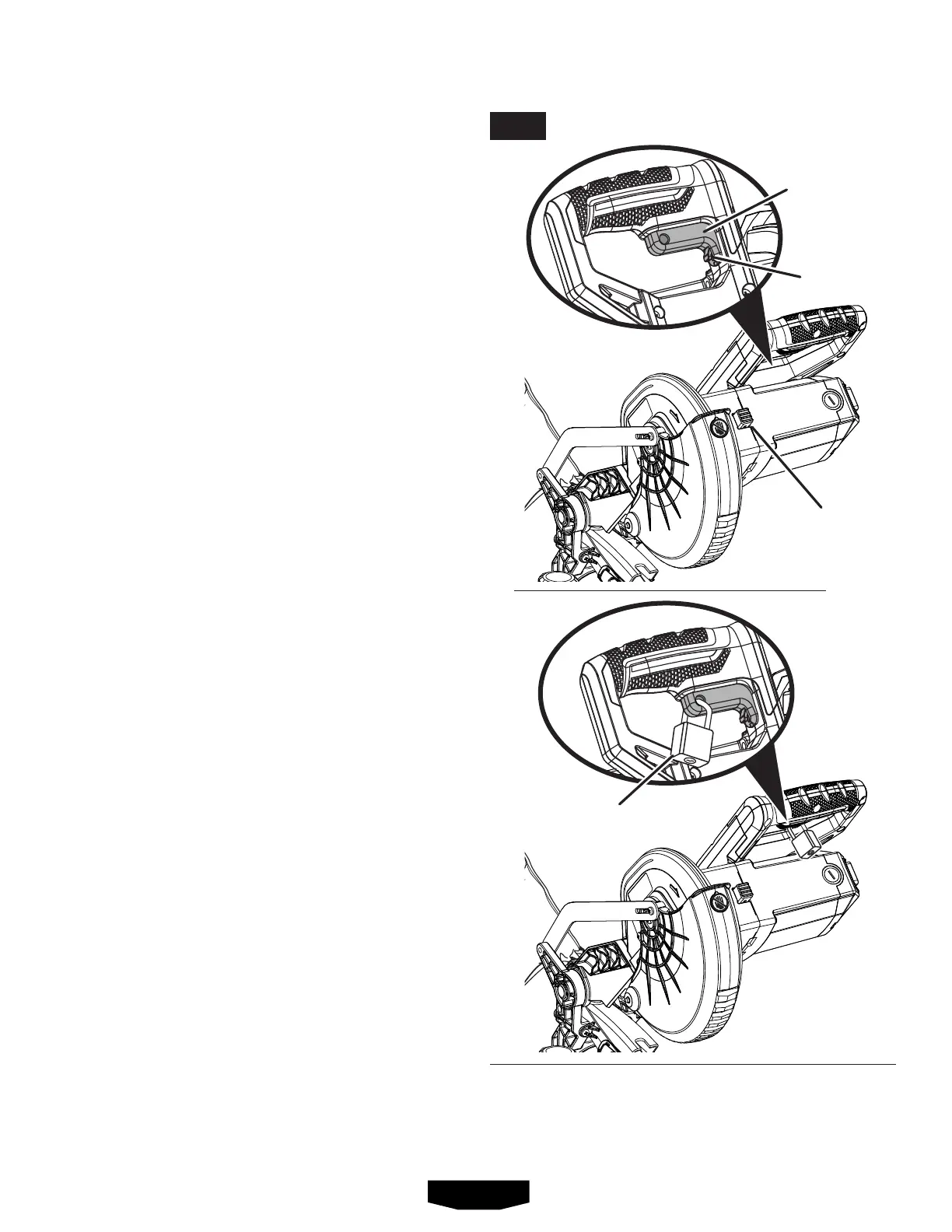
SPINDLE LOCK BUTTON
See Figure 5.
Thespindlelockbuttonlocksthespindlestoppingtheblade
fromrotating.Depressandholdthelockbuttonwhileinstall-
ing,changing,orremovingblade.
SWITCH TRIGGER
See Figure 5.
Thesawwillnotstartuntilyoudepressthetriggerlockout
leverandsqueezetheswitchtrigger.Topreventunauthor-
izeduseofthe compound mitersaw, disconnectitfrom
thepowersupplyandlocktheswitchintheOFFposition.
Tolocktheswitch,installapadlock(notincluded)through
theholeintheswitchtriggerandmakecertaintheswitch
isinoperable.Iftheswitchisstilloperablewiththepadlock
installed,apadlockwithalargershacklediametermustbe
used.Storethepadlockkeyinanotherlocation.
PADLOCK
SPINDLE
LOCK BUTTON
TRIGGER
LOCKOUT
LEVER
SWITCH
TRIGGER
FEATURES
FIG. 5