15 – English
WARNING:
This saw can tip over if the saw head is released
suddenlyandthesawisnotsecuredtoaworksurface.
ALWAYS secure this saw to a stable work surface
beforeanyusetoavoidseriouspersonalinjury.
MOUNTING HOLES
See Figure 8.
WARNING:
Beforestartingany cutting operation, clamp or bolt
yourmitersawtoaworkbenchoranapprovedmiter
sawstand.Ifamitersawstandisused,readoperator’s
manualandfollowtheinstructionsforthemitersaw
stand.Neveroperateyourmitersawonthefloororin
acrouchedposition.Failuretoheedthiswarningcan
resultinseriouspersonalinjury.
Thecompoundmitersawshouldbemountedtoafirmsup-
portingsurfacesuchasaworkbench,mountingboard,or
mitersawstand.Thesawbasehasfourmountingholes.If
usingboltsorscrews,theyshouldbeofsufficientlengthto
accommodatethesawbase,lockwashers,hexnuts,and
thethicknessoftheworkbenchorothermountingsurface.
Tightenallboltsorscrewssecurely.
Theholepatternformountingtoaworkbenchisshownin
figure 8.Carefullychecktheworkbenchaftermountingto
makesurethatnomovementcanoccurduringuse.Ifany
tipping,sliding,orwalkingisnoted,securetheworkbench
tothefloorbeforeoperating.
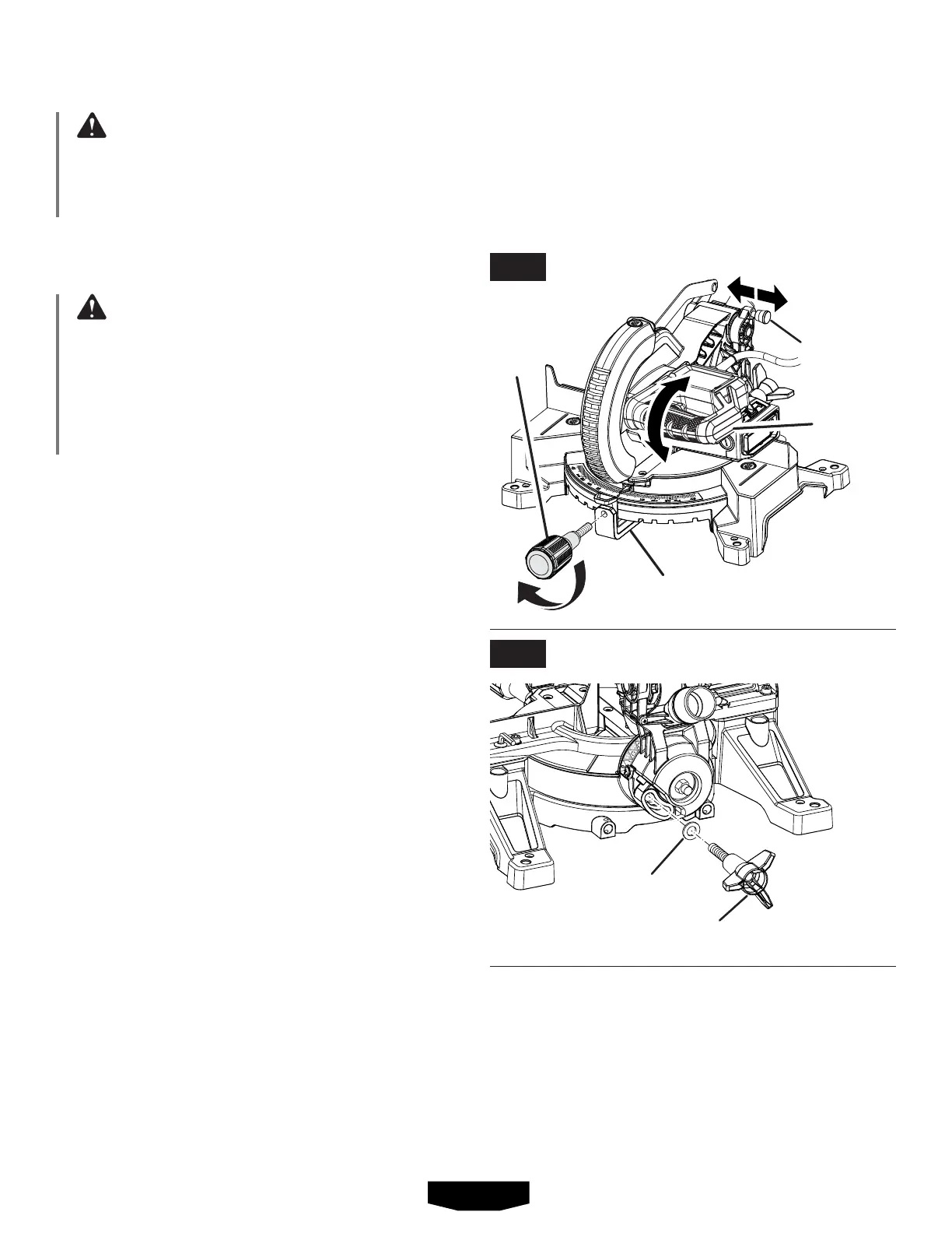
MITER LOCK KNOB
See Figure 9.
Toinstallthemiterlockknob,placethethreadedstudon
theendofthemiterlockknobintothethreadedholeinthe
controlarm.Turnclockwisetotighten.
LOCKING/UNLOCKING THE SAW ARM
See Figure 9.
To unlock and raise the saw arm:
Firmlygraspthe“D”handleandapplydownwardpres-
surewhileatthesametimepullingthelockpinoutand
awayfromthesawhousing.
Releasethelockpinandslowlyraisethesawarm.
To lock the saw arm:
Firmlygraspthe“D”handleandapplydownwarduntil
theheadcomestoastop,thenpushthelockpininand
towardthesawhousing.
Releasethelockpinallowingittolockthesawintoplace.
“D”
HANDLE
LOCK
PIN
INSTALLING THE BEVEL LOCK KNOB
See Figure 10.
To install thebevellockknob,slide the washer onto the
threadedstudontheendofthebevellockknobthenplace
theknobintothethreadedholeonthebackofthesaw.Turn
clockwisetotighten.
CONTROL ARM
MITER
LOCK
KNOB
BEVEL LOCK
KNOB
WASHER
ASSEMBLY
FIG. 9
FIG. 10