20 – English
SQUARING THE BLADE TO THE MITER TABLE
See Figures 22 - 24.
Unplugthesaw.
Pullthesawarmallthewaydownandengagethelock
pintoholdthesawarmintransportposition.
Loosenthemiterlockknobapproximatelyone-halfturn
andpressthedetentreleasebutton.
Rotatethemitertableuntilthescaleindicatorisposi-
tionedat0°.
Releasethedetentreleasebutton,engagingthepositive
stopnotch,thentightenthemiterlockknobtosecurethe
mitertable.
Tightenthemiterlockknobtosecurethemitertable.
Loosenbevellockknobandsetsawarmat0
°
bevel(blade
set90
°
tomitertable).Tightenbevellockknobatstop.
Placeacombinationsquareagainstthemitertableand
theflatpartofsawblade.
NOTE: Makesurethatthesquarecontactstheflatpart
ofthesawblade,notthebladeteeth.
Rotatethebladebyhandandchecktheblade-to-table
alignmentatseveralpoints.
The edgeofthe squareand thesaw bladeshouldbe
parallelasshowninfigure 22.
Ifthetoporbottomofthesawbladeanglesawayfrom
thesquareasshowninfigures 23 and 24,adjustmentsare
needed.
Loosenthebevellockknob.
Adjustpositivestopadjustmentscrewtobringsawblade
intoalignmentwiththesquare.SeePositive Stop Adjust-
mentintheAdjustments section.
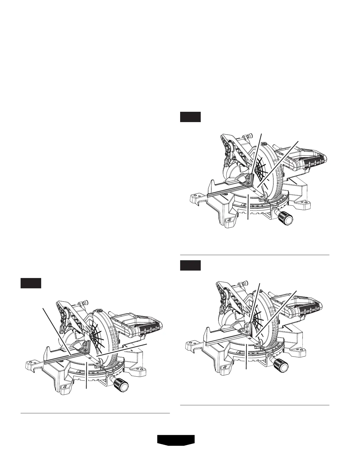
VIEW OF BLADE NOT SQUARE WITH MITER
TABLE, ADJUSTMENTS ARE REQUIRED
VIEW OF BLADE NOT SQUARE WITH MITER TABLE,
ADJUSTMENTS ARE REQUIRED
VIEW OF BLADE SQUARE WITH MITER TABLE
Retighten bevel lock knob.Recheckblade-to-table
alignment.
NOTE: Theaboveprocedurecanbeusedtocheckblade
squarenessofthesawbladetothemitertableatboth0
°
and 45
°
angles.
Thesawhastwoscaleindicators,oneonthebevelscaleand
oneonthemiterscale.Aftersquaringadjustmentshavebeen
made,itmaybenecessarytoloosentheindicatorscrews
andresetthemtozero.See figures 20 - 21.
MITER
TABLE
MITER
TABLE
MITER
TABLE
COMBINATION
SQUARE
COMBINATION
SQUARE
COMBINATION
SQUARE
BLADE
BLADE
BLADE
ASSEMBLY
FIG. 22
FIG. 23
FIG. 24