3.
INSTRUCTIONS FOR INSTALLATION 3. INSTALLATIONSANLEITUNG
3. 1. Before Installation
Befo re installing the heater, study the instructions
3.
1. Vor der Montage
Bevor Sie den Saunaofen inst alliere,n
lesen Sie die
for installation. Check the following points:
ls the output and type of the heater suitable for
the sauna room?
The cubic volumes given in
table 2 should be fo llow ed .
ls the supply voltage suitable for the heater?
•
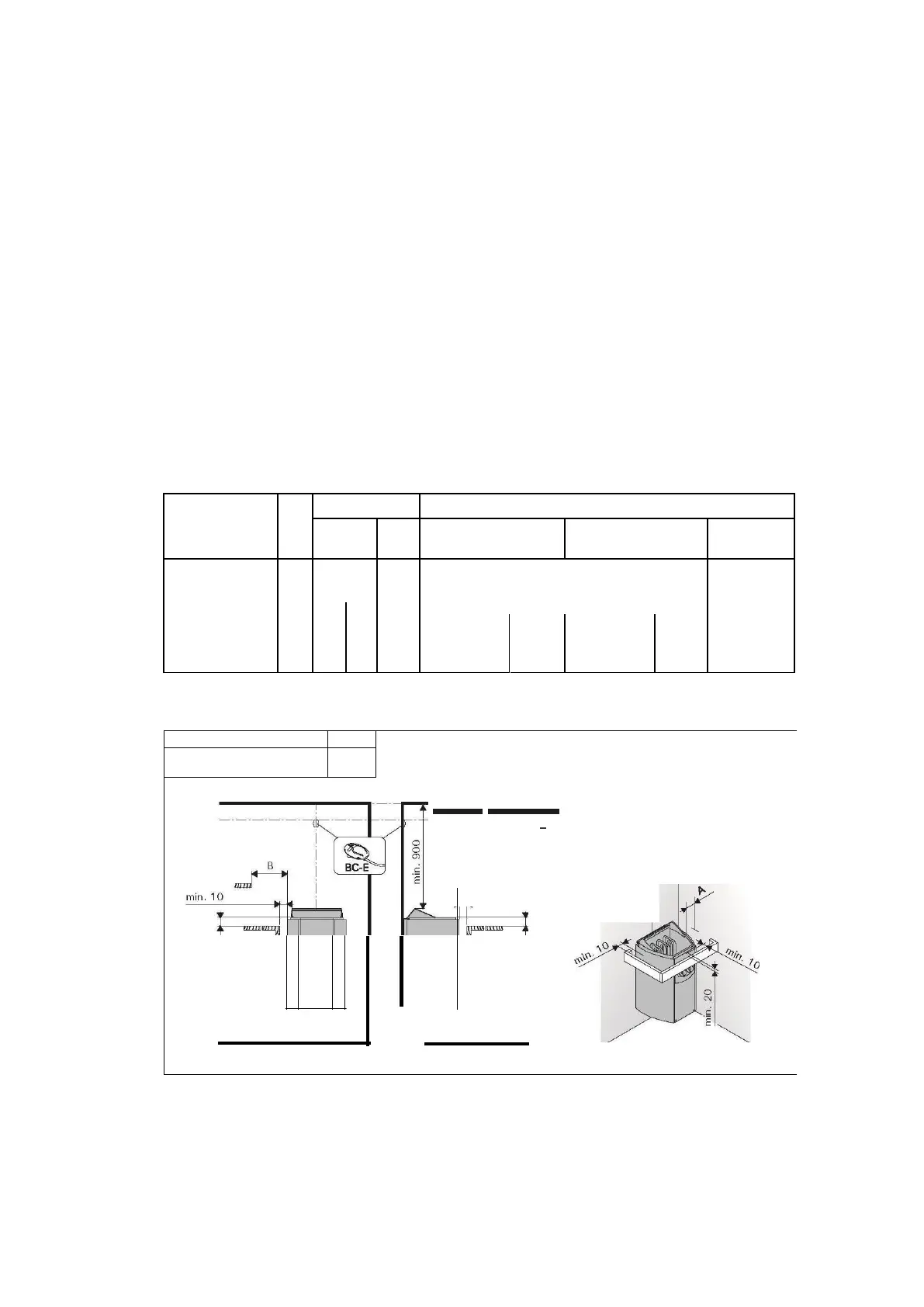
The location of the heater fulfils the minimum
requirements concerning safety distances given
in fig. 6 andtable 2.
lt
is
absolutely necessary to install the heater ac-
cording to these values. Neglecting them causes
a risk of fire. Only one electrical heater may be
installed in the sauna room.
Montageanleitung und überprüfen Sie folgende Din-
ge:
• Ist der zu montierende Saunaofen in Leistung
und Typ passend für die Saunakabine?
Die
Rauminhaltswerte in Tabelle 2 dürfen weder
über noch unterschritten werden.
•
Ist die Netzspannung für den Saunaofen geeig-
net?
•
Der Mont ageort des Ofens erfüllt die in Abbil-
dung 6 und Tabelle 2 angegebenen Sicherheits-
mindestabstände.
Diese Abstände müssen unbedingt eingehalten
werden, da ein Abweichen Brandgefahr verursacht.
In einer Sauna darf nur ein Saunaofen installiert
werden.
Heater
Ofen
M odel and
dim ensions/
M ode ll und Maße
Electrical connections
Elektroanschlüsse
400 V 2N~
Connecting
cable
I
Fuse
Anschlusskabel Sicherung
230 V 1N ~
Connecting
cable
I
F
use
Anschlusskabel Sicherung
Widt h/Brei te 280 mm
Depth/Tieef
•
BC 295 mm
•
BC-E 270 mm
Height/Höhe 505 mm
Weight/Gew icht 7 kg
Stones/Steine
max. 12 kg
Seefig.
7.
The
measurementsapply
to
theconnecting
cabel
only!
Siehe Abbildung 7, Die Messungen bezieh en sich
ausschließlich auf das Anschlusskabel!
Table 2. Installation details
Tabelle 2. Montageinformationen
··· ···
r
m in.
1 0
W---1-------
0
"'
C
E
80 - 2 00
Figure 6.
Abbildung 6.
Safety distances (all dimensions in millimeters)
Sicherheitsmindestabstände (alle Abmessungen in Millimetern)
10