EN DE
11
3. INSTRUCTIONS FOR INSTALLATION
3.1. Prior to Installation
Prior to installing the heater, study the instructions
for installation, as well as checking the following
points:
Is the output and type of the heater suitable for
the sauna room?
The cubic volumes given in table 1 should be
followed.
As for the mounting place, the heater is right-
handed
Are there a sufficient number of high quality
sauna stones?
Is the supply voltage suitable for the heater?
If the house is heated by electricity, does the
pilot circuit (contactor) require a supplementary
relay to make the pilot function potentialfree,
because voltage control is transmitted from the
heater when it is switched on?
The location of the heater fulfils the minimum
requirements concerning safety distances given
in fig. 5 and 6 and table 1.
It is absolutely necessary to ensure that the installation
is carried out according to these values. Neglecting
them can cause a risk of fire. Only one electrical
heater may be installed in the sauna room.
•
•
•
•
•
•
3. ANLEITUNG FÜR DEN INSTALLATEUR
3.1. Vor der Montage
Bevor Sie den Saunaofen installieren, lesen Sie die
Montageanleitung und überprüfen Sie folgende
Dinge:
Ist der zu montierende Saunaofen in Leistung und
Typ passend für die Saunakabine?
Die Rauminhaltswerte in Tabelle 1 dürfen weder über
noch unterschritten werden.
Die Anschlußrichtung ist in Bezug auf den
Montageort rechtsseitig.
Sind genug Saunaofensteine von guter Qualität
vorhanden?
Ist die Netzspannung für den Saunaofen geeignet?
Falls das Haus elektrisch beheizt wird, benö
-
tigt der Steuerkreis (Kontaktor) der Heizung ein
Zwischenrelais, um die Steuerfunktion auf poten
-
tialfrei zu stellen, da vom Saunaofen bei Gebrauch
eine Spannungssteuerung übertragen wird.
Der Montageort des Ofens erfüllt die in Abbildung
5 und 6 und Tabelle 1 angegebenen Sicherheits
mindestabstände.
Diese Abstände müssen unbedingt eingehalten wer-
den, da ein Abweichen Brandgefahr verursacht. In
einer Sauna darf nur ein Saunaofen installiert wer-
den.
•
•
•
•
•
•
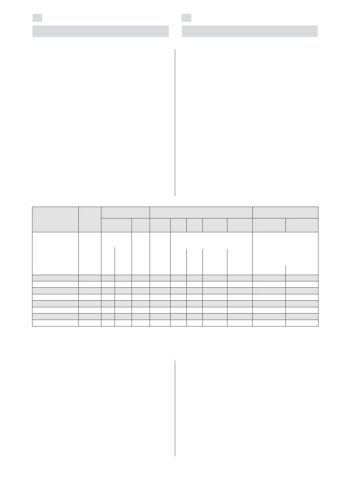
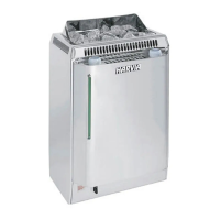
Table 1. Installation details of a BC/BCE heater
Tabelle 1. Montageinformationen zum BC/BCE-Saunaofen
*) To thermostat 4 x 0,5 mm
2
*) An Thermostat 4 x 0,5 mm
2
Heater/Ofen
Model and
dimensions/
Modell und Maße
Output
Leistung
kW
Sauna room
Saunakabine
Minimum distances
Min. Abstand des Ofen
Connecting cable/Fuse
Anschlußkabel/Sicherung
Cubic vol.
Rauminhalt
Height
Höhe
A
min.
B
min.
C
min.
to ceiling
zur Decke
to floor
zum Boden
400V 3N~
Fuse
Sicherung
Width/Breite
• BC 480 mm
• BCE 450 mm
Depth/Tiefe
310 mm
Height/Höhe 540 mm
Weight/Gewicht 11 kg
Stones/Steine
max. 25 kg
See item 2.3.
siehe Kap.
2.3.
min.
mm
See
fig. 6.
Siehe
Abb. 6.
See fig. 5.
Siehe Abbildung 5.
See fig. 8. The measurements
apply to the connection cable
only!
Siehe Abbildung 8. Die
Messungen beziehen sich
ausschließlich auf das
Anschlusskabel!
min.
m
3
max.
m
3
mm mm mm mmmm mm
2
A
BC45 4,5 3 6 1900 35 20 35 1100 80 5 x 1,5 3 x 10
BC60 6,0 5 8 1900 50 30 50 1100 80 5 x 1,5 3 x 10
BC80 8,0 7 12 1900 100 30 80 1100 80 5 x 2,5 3 x 16
BC90 9,0 8 14 1900 120 40 100 1100 80 5 x 2,5 3 x 16
BC45E 4,5 3 6 1900 35 20 35 1100 80 5 x 1,5 *) 3 x 10
BC60E 6,0 5 8 1900 50 30 50 1100 80 5 x 1,5 *) 3 x 10
BC80E 8,0 7 12 1900 100 30 80 1100 80 5 x 2,5 *) 3 x 16
BC90E 9,0 8 14 1900 120 40 100 1100 80 5 x 2,5 *) 3 x 16
3.2. Fastening the Heater on a Wall
1. Fasten the wall-mounting rack on the wall by
using the screws which come with the rack.
Observe the minimum safety distances given in
table 1 and fig. 5 and 6.
NOTE! There must be a support, e.g. a board,
behind the panel, so that the fastening screws can
be screwed into a thicker wooden material than the
panel. If there are no boards behind the panel, the
boards can also be fastened on the panel.
2. Lift the heater to the rack on the wall so that
the fastening hooks of the lower part of the rack
go behind the edge of the heater body.
3. Lock the edge of the heater onto the fastening
rack by a screw.
3.2. Befestigung des Saunaofens an der Wand
1. Befestigen Sie das Montagegestell mit den
dazu gelieferten Schrauben an der Wand und
beachten Sie die in Abb. 5 und 6 und in Tabelle
1 angeführten Sicherheitsmindestabstände.
ACHTUNG! An den Stellen, an denen die
Befestigungsschrauben angebracht werden, muss
sich hinter den Paneelen als Stütze z.B. ein Brett
befinden, in dem die Schrauben fest sitzen. Falls sich
hinter den Paneelen keine Bretter befinden, können
diese auch vor den Paneelen angebracht werden.
2. Heben Sie den Saunaofen so auf das Gestell an
der Wand, daß die Befestigungshaken unten am
Gestell hinter den Rand des Saunaofenrumpfes
kommen.
3. Schrauben Sie den oberen Rand des
Saunaofens am Montagegestell fest.