EN DE
15
3.6.1. Resetting the Overheat Protector
(BC45, BC60, BC80, BC90)
The reset button is located on the thermostat frame
on the electrical box (see fig. 12), and consequently,
the fuses of the heater on the electrical panel must
be removed before commencing the work.
1. Detach the turnable levers of the thermostat and
the timer by pulling them outwards.
2. Detach the M4x5 screw below the timer lever.
3. Detach the fastening screws (2) of the connection
box cover on the lower end of the box, and
remove the cover of the connection box.
Reset the limit stop by pressing (with 7 kg force
if necessary) so that a clicking sound is heard. See
figure 12.
3.7. Electric Heater Insulation Resistance
When performing the final inspection of the electrical
installations, a “leakage” may be detected when meas
-
uring the heater’s insulation resistance. The reason
for this is that the insulating material of the heating
resistors has absorbed moisture from the air (storage
transport). After operating the heater for a few times,
the moisture will be removed from the resistors.
Do not connect the power feed for the heater
through the RCD (residual current device)!
3.6.1. Rücksetzung des Überhitzungsschutzes
(BC45, BC60, BC80, BC90)
Der Rücksetzknopf befindet sich in der Elektrobuchse
im Rahmenteil des Thermostats (siehe Abb. 12),
daher müssen die Saunaofensicherungen an der
Elektrotafel zunächst gelöst werden.
1. Entfernen Sie die Drehhebel des Thermostats und
die Zeitschaltuhr, indem Sie sie herausziehen.
2. Lösen Sie die Schraube M4x5 unter dem Hebel
der Zeitschaltuhr.
3. Lösen Sie die Sicherungsschrauben (2) der
Schaltergehäuseabdeckung am unteren Ende
des Gehäuses und entfernen Sie die Abdeckung
des Schaltergehäuses.
Der Begrenzer wird durch Druck in seine
Funktionsstellung zurückgesetzt (bei Bedarf mit einer
Kraft, die 7 kg entspricht), im Begrenzer ist dann ein
Knacken zu hören. Siehe Abbildung 12.
3.7. Isolationswiderstand des Elektrosaunaofens
Bei der Endkontrolle der Elektroinstallationen kann
bei der Messung des Isolationswiderstandes ein
“Leck” auftreten, was darauf zurückzuführen ist, daß
Feuchtigkeit aus der Luft in das Isolationsmaterial
der Heizwiderstände eingetreten ist (bei Lagerung
und Transport). Die Feuchtigkeit entweicht aus den
Widerständen nach zwei Erwärmungen.
Schalten Sie den Netzstrom des Elektrosaunaofens
nicht über den Fehlerstromschalter ein!
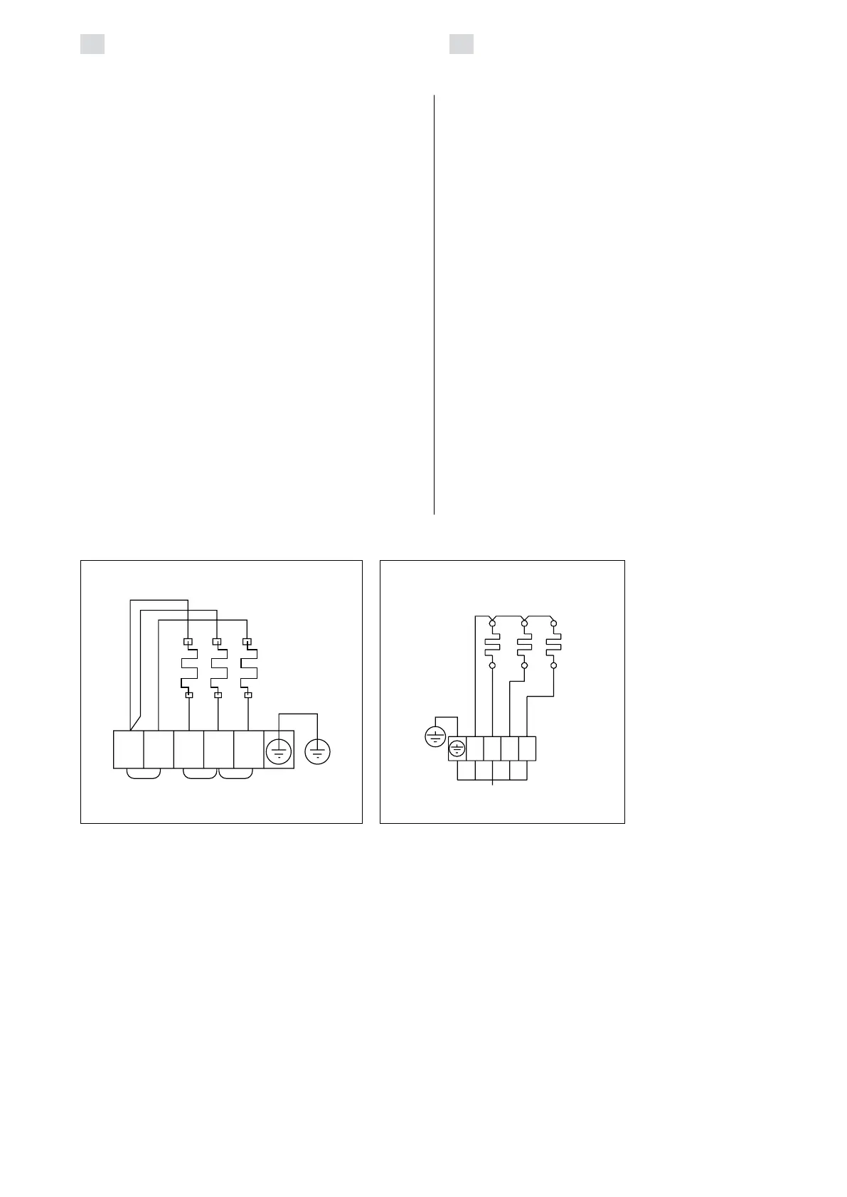
Figure 10a. Electrical connections of 4,5
and 6,0 kW heater
Abbildung 10a. Elektroanschlüsse des 4,5
und 6,0 kW Saunaofens
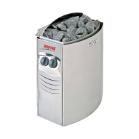
Figure 10b. Electrical connections of
BCE heater
Abbildung 10b. Elektroanschlüsse des
Saunaofens BCE
400 V 3N~
1
2 3
N L1L2L3
BC45E, BC60E,
BC80E, BC90E