EN DE
16
brennbarer Materialien vor der Hitze des Ofen. (Nur
M2, M3, M3 SL, 20 Pro, 20 ES Pro/S, Classic 220
Linear, 22, Legend 150 und Legend 150 SL).
3.2. Montage des Ofens
3.2.1. Verstellbare Füße des Ofens (Außer bei Mo-
dellen M2/M3/M3 SL)
Die verstellbaren Füße dienen zur sicheren Installati-
on auf schiefer Grundäche. Regelbereich 0–30 mm.
Die verstellbaren Füße sollten bis zu einem Ausmaß
gelöst werden, das es ermöglicht, sie mit einem Ga-
belschlüssel (17 mm) einzustellen, wenn der Ofen an
seinem Platz steht.
Die verstellbaren Füße können die Bodenober-
fläche zerkratzen, wenn der Ofen auf dem
Boden bewegt wird.
3.2.2. Anschluss des Ofens an einen gemauerten
Rauchfang
Stellen Sie in der Brandmauer eine Öffnung für den
Abzugsanschluss her. Beachten Sie, falls Sie z.B.
eine Schutzplatte anzubringen gedenken, dass sich
die Öffnung auf der richtigen Höhe benden muss.
Das Loch sollte etwas größer sein als der Durchmesser
des Abzugsanschlussrohres. Eine Dichtungslücke von
etwa 10 mm um das Rohr herum ist angemessen. Es
ist ratsam, die inneren Ecken der Rauchfangsöffnung
abzurunden, damit die Rauchgase in den Rauchfang
frei abziehen können. Zur einfacheren Montage steht
zusätzliches Zubehör zur Verfügung ( 3.4.).
M2, M3/SL, 20 Pro/SL, 20 ES Pro/S, 20 Boiler/SL,
Classic 220, Linear 22, 22: Anschluss des Ofens an
einen gemauerten Rauchfang über die hintere An-
schlussöffnung (Abbildung 10)
1. Biegen Sie den Deckel nach unten (nur M2/
M3). Bringen Sie das Abzugsanschlussrohr an
die hintere Anschlussöffnung an. Das Rohr muss
fest an seinem Platz sitzen.
2. Schieben Sie den Ofen an seine Position.
Schieben Sie das Abzugsanschlussrohr nicht zu
weit in den Rauchfang hinein. Kürzen Sie das
Rohr, falls notwendig.
3. Dichten Sie das Abzugsanschlussrohr in der
1
3
2
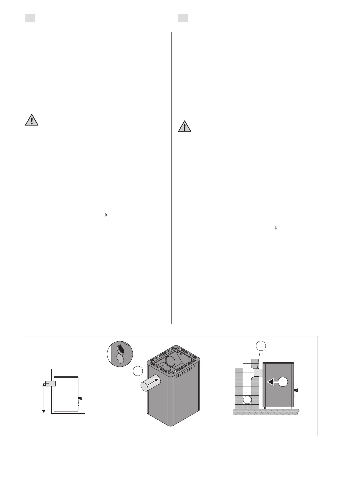
560
Figure 10. Connecting the stove to a masonry flue via the rear connection opening (all dimensions in millimeters)
Abbildung 10. Anschluss des Ofens an einen gemauerten Rauchfang über die hintere Anschlussöffnung (alle
Abmessungen in Millimetern)
mable materials from the heat of the stove. (For models
M2, M3, M3 SL, 20 Pro, 20 ES Pro/S, Classic 220,
Linear 22, 22, Legend 150 and Legend 150 SL only).
3.2. Installing the Stove
3.2.1. Adjustable Legs (excluding the models M2/
M3/M3 SL)
The adjustable legs enable the stove to be installed
rmly on an inclined oor. The adjustable range is
0–30 mm. Unscrew the adjustable feet to an extent
that allows them to be adjusted using a wrench
(17 mm) when the stove is in position.
The adjustable feet could scratch the floor
surface if the stove is moved on the floor.
3.2.2. Connecting the Stove to a Masonry Flue
Make an opening in the reproof wall for the ue
connection. Notice that the opening has to be at the
correct height, if you intend to use, for instance, a
protective bedding. The hole should be slightly larger
than the ue connecting pipe. A suitable gap around
the connection pipe is ca. 10 mm. It is advisable to
round off the inner corners of the ue opening to
ensure that the combustion gases can ow freely
to the ue. Additional accessories are available to
make the installation easier ( 3.4.).
M2, M3/SL, 20 Pro/SL, 20 ES Pro/S, 20 Boiler/SL,
Classic 220, Linear 22, 22: Connecting the stove
to a masonry flue via the rear connection opening
(figure 10)
1. Bend the cover hatch downwards (M2/M3
only). Attach the ue connection pipe to the
rear connection opening. Ensure that the pipe
ts tightly in place.
2. Push the stove into place. Do not block the ue
by pushing the ue connection pipe too far into
the ue. If necessary, shorten the pipe.
3. Seal the ue connection pipe to the opening
in the reproof wall, for example, by using
reproof mineral wool. Make sure that the ue
connection is tightly sealed. Add more reproof
mineral wool if necessary.
 Loading...