Do you have a question about the Haswill STC-9200 and is the answer not in the manual?
Configures the desired temperature set-point for the thermostat. Adjusts the primary target temperature.
Defines the temperature difference for switching loads on/off, preventing rapid cycling.
Sets the frequency for defrosting cycles, determining how often defrosting occurs.
Specifies the duration for each defrosting cycle, controlling how long it runs.
Sets the evaporation temperature threshold to end the defrosting process.
Selects the method for defrosting, either electric heating or hot gas from compressor.
Configures time delay for the fan operation relative to compressor start/stop.
Determines how the fan operates, based on temperature, continuous, or delayed start.
Sets the room temperature threshold to trigger a high-temperature alarm.
Sets the room temperature threshold to trigger a low-temperature alarm.
Configures a delay before triggering an alarm based on room sensor temperature.
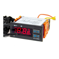
The STC-9200 Thermostat is a digital temperature controller designed to manage three distinct loads: a refrigeration device, a defrosting unit, and an evaporator fan. This controller is particularly well-suited for use in oversized freezer rooms, where precise temperature management and efficient defrosting are critical.
The primary function of the STC-9200 is to maintain a desired temperature range within a controlled environment, typically a freezer room. It achieves this by intelligently operating the refrigeration compressor, initiating defrost cycles, and managing the evaporator fan. The controller allows users to set a target temperature (SP) and a temperature hysteresis (HY), ensuring that the room temperature remains within the specified bounds.
The defrosting function is a key feature, controlled by both time and temperature conditions. The unit can be configured for different defrosting modes, including electric heating or hot gas from the compressor. This dual control mechanism helps prevent excessive defrosting, which can be energy-intensive, while ensuring that ice buildup does not impede the refrigeration system's efficiency. The evaporator fan's operation is also integrated into the control logic, with various modes to optimize cooling and defrosting processes.
An alarm function is built into the STC-9200, providing alerts based on room sensor temperature deviations. This ensures that users are promptly notified of any critical temperature changes or sensor malfunctions, enhancing the safety and reliability of the controlled environment.
The STC-9200 offers a user-friendly interface for setting and adjusting its operational parameters. Users can define the target temperature range by setting the Temperature Set-Point (F1/SEE) and the Temperature Hysteresis/Return Difference (F2/HY). The controller also includes upper and lower limits for the set-point (F3/US and F4/LS), preventing settings that might be outside safe or desired operating parameters.
Configuring the defrosting process involves several adjustable parameters. Users can set the Defrosting Cycle/Interval Time (F6/dF) to determine how often defrosting occurs. The Defrosting Lasting/Running Time (F7/AdF) specifies the duration of each defrost cycle. To prevent over-defrosting, a Defrosting Stop Temperature (F8/dEE) can be set, which halts the defrost process once the evaporator sensor reaches this temperature. The Defrosting Water Dripping Time (F9/FdL) allows for a period after defrosting for water to drain, preventing refreezing.
The controller supports two Defrosting Modes (F10/EdF): Electric-Heating (0/EL) and Hot Gas from the compressor (1/HEG). The choice of mode depends on the specific setup and efficiency requirements. The Count mode of defrost cycle (F11/dEc) can be set to either cumulative time from controller power-on (0/rt) or cumulative time of the compressor working (1/CoH), providing flexibility in how defrost cycles are triggered. During defrosting, the display mode (F12/dFd) can show either the room sensor temperature (0/rt) or the evaporator sensor temperature (1/Et), with the latter continuing for 10 minutes after defrosting to provide useful diagnostic information.
The evaporator fan's operation is highly customizable. The Time delay seconds for the Fan (F15/Fod) parameter is crucial. If F15 is less than 0, it defines the period for the fan to start earlier than the compressor and stop when defrosting begins. If F15 is greater than or equal to 0, the fan's operation is controlled by F13 (FnC), which offers three output modes:
The alarm settings are also configurable. Users can set the Upper Temperature of the Room sensor to Trigger Alarm (F17/ALU) and the Lower Temperature of the Room sensor to Trigger Alarm (F18/ALL). A Time delay of the Room sensor to Trigger Alarm (F19/ALD) can be set to prevent nuisance alarms from momentary temperature fluctuations. Finally, a Temperature Calibration (F20/oE) parameter allows for fine-tuning the sensor readings to match the actual measured temperature, ensuring accuracy.
While the provided document is a quick start guide, it implies certain maintenance considerations through its detailed parameter settings. The ability to calibrate the temperature sensor (F20/oE) is a key maintenance feature, allowing users to ensure the accuracy of temperature readings over time. This is crucial for maintaining optimal performance and preventing issues related to incorrect temperature control.
The alarm function, particularly its ability to detect a broken evaporator sensor, serves as a diagnostic tool, aiding in early detection of potential system failures. This proactive alert system helps in scheduling timely maintenance or repairs, preventing more significant damage or loss of refrigerated goods.
The various defrosting parameters, such as the Defrosting Stop Temperature (F8/dEE) and Defrosting Water Dripping Time (F9/FdL), contribute to the longevity and efficiency of the refrigeration system by preventing excessive ice buildup and ensuring proper drainage. Proper configuration of these settings can reduce wear and tear on components and minimize the need for manual intervention.
The detailed control over the evaporator fan, including its startup and stop conditions based on temperature or defrost cycles, helps in optimizing its operation, potentially extending its lifespan and reducing energy consumption. By allowing for precise adjustments to these operational parameters, the STC-9200 enables users to tailor the system's behavior to specific environmental conditions and operational demands, thereby contributing to overall system health and reduced maintenance frequency.
In summary, the STC-9200 Thermostat is a comprehensive digital controller offering robust functionality for managing refrigeration, defrosting, and fan operations in freezer rooms. Its extensive range of adjustable parameters, coupled with diagnostic and alarm features, makes it a versatile and reliable solution for maintaining stable temperatures and efficient operation.
| Power supply | 110-220V AC ±10%, 50/60Hz |
|---|---|
| Relay capacity | 10A/220VAC |
| Input | NTC sensor |
| Output | Cooling and heating relay outputs |
| Sensor cable length | 2 meters |
| Dimensions | 75mm x 34mm x 85mm |
| Alarm | High and low temperature alarm |
| Display | LED display |
| Type | Digital thermostat |