"'( (#"
8
Form No. DHLM-1010
<AB/::7<5$'/<2&!=C<B)<7BA
(C@<>=E3@#/B;=C<B7<5:=1/B7=<034=@37<AB/::/B7=<=4
C<7B
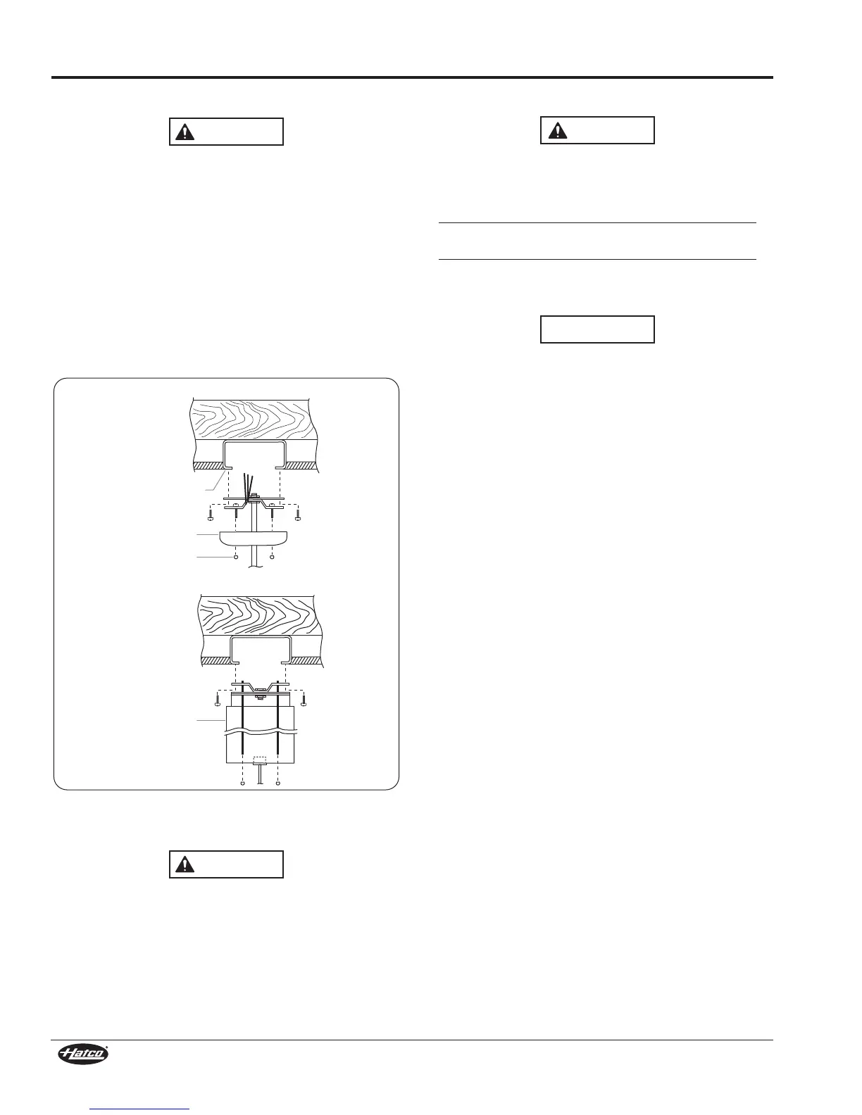
1. Mount the top bracket to a 4" (102 mm) octagon junction
box using the two screws provided with the junction box.
2. Make sure all power is OFF, and connect supply lead L1 to
the black lamp lead. Connect neutral to the white lamp
lead.
If the lamp is equipped with three wires, connect ground to
the green lead. If lamp is equipped with two wires, make
proper ground wire connections from junction box. Tuck
excess wires into junction box.
3. Slide the canopy cover or cord housing up until it rests
against the ceiling and install the two ball cap nuts until
snug to the ceiling.
Figure 7. Mounting to a Junction Box
<AB/::7<5('!=C<B)<7BA) &31=5<7H32
(C@<>=E3@#/B;=C<B7<5:=1/B7=<034=@37<AB/::/B7=<=4
C<7B
1. Drill a 7/16" (11 mm) hole through mounting fixture.
2. Pass wires from the Decorative Heat Lamp through hole in
fixture.
3. Secure Decorative Heat Lamp to fixture with nut.
4. Make sure all power is OFF, and connect supply lead L1 to
the black lamp lead. Connect neutral to the white lamp lead
and the ground to the green lead.
A, C, P, and S Mount
Junction Box
R Mount
Ball Cap Nuts
Canopy
Adjustable Cord
Housing
<AB/::7<5(@/19!=C<B)<7BA('(/<2&(
(63 ;/F7;C; 1/>/17BG =4 $=E3@(@/1 B@/19 :756B7<5
AGAB3;A 7A >3@ 17@1C7B 6319 4CA3A /<2 17@1C7BA
1/@34C::G034=@37<AB/::7<5(63;/F7;C;7<1:C23A/::
:756BA /<2 />>:7/<13A 1=<<31B32 B= 17@1C7B * =<:G
;/F7;C;+>3@/<G:3<5B6B@/19
$=E3@(@/1AGAB3;A/@3<=B7<B3<2324=@CA3E7B6/>=E3@
AC>>:G1=@2=@1=<D3<73<13@313>B/1:3/2/>B3@
+63<7<AB/::7<5B@/19:756B7<5AGAB3;ACA3=<:G47FBC@3
/AA3;0:73A ;/@932 4=@ CA3 E7B6 #
M
(@/1 /<2 (@/1
7BB7<5A;/@9324=@CA3E7B6 '3@73A(@/1
/B1= 63/B :/;>A/@30C7:BB=47B #
M
0@/<2
/<2 $=E3@(@/1B@/19:756B7<5AGAB3;A=<:G=
<=B/BB3;>BB=CA3=</<G=B63@B@/19:756B7<5AGAB3;
The Trac system is to be supplied by a single branch circuit
120 V, 60 Hz, 20 A.
NOTE: A maximum of nine 200 W luminaire units, seven 250 W
heat lamp units, or five 375 W heat lamp units may be
installed per each 120 V, 20 A track bar circuit. The
Installer is responsible for properly sizing the supply
circuit with the lamp load.
Hatco provides track kits in three different lengths:
• L651 — 4 ft. (1219 mm)
• L652 — 8 ft. (2438 mm)
• L653 — 12 ft. (3658 mm)
When installing or using this Trac system, the following basic
safety precautions should always be followed:
• Read all of these installation instructions before installing
the Trac system.
• Save these instructions and refer to them when additions
to or changes in the Trac configuration are made.
• Do not install this Trac in damp or wet locations.
• Do not install any part of a Trac system less than 5 feet
(1524 mm) above the floor.
• Do not install any fixture assembly closer than 1" (25 mm)
along the sides from any curtain or similar combustible
material.
• Disconnect electrical power before adding to or changing
the configuration of the Trac.
• Do not attempt to energize anything other than Trac lighting
fixtures on the Trac. To reduce the risk of fire and electric
shock, do not attempt to connect power tools, extension
cords, appliances, etc. to the Trac.