EasyManua.ls Logo

Hatco DL-400 User Manual

Hatco DL-400
20 pages
To Next Page IconTo Next Page
Page #1 background imageLoading...
Page #1 background image
Decorative Heat Lamps
DL Series
Installation &
Operating Manual
I&W #07.05.147.00
This manual contains important safety information
concerning the maintenance, use and operation of this
product. Failure to follow the instructions contained in this
manual may result in serious injury. If you’re unable to
understand the contents of this manual, please bring it to
the attention of your supervisor. Do not operate this
equipment unless you have read and understood the
contents of this manual.
Este manual contiene importante información sobre
seguridad concerniente al mantenimiento, uso y
operación de este producto. Cualquier falla en el
seguimiento de las instrucciones contenidas en este
manual puede resultar en un serio daño. Si usted no
puede entender el contenido de este manual por
favor pregunte a su supervisor. No opere este
equipo al menos que haya leído y comprendido el
contenido de este manual.
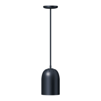
Other manuals for Hatco DL-400

Questions and Answers:

Hatco DL-400 Specifications

General IconGeneral
BrandHatco
ModelDL-400
CategoryIndoor Furnishing
LanguageEnglish

Summary

Important Owner Information

Record Owner Information

Record model number, serial number, voltage, and purchase date for service assistance.

Introduction to Decorative Heat Lamps

Product Description and Purpose

Hatco Decorative Heat Lamps are designed for food serving temperatures and decor enhancement.

Safety Instructions Overview

Manual provides installation, safety, and operating instructions; emphasizes reading warnings.

Important Safety Information: Electrical and Maintenance

Electrical Safety and Grounding

Ensure proper grounding, avoid water submersion, and do not use excessive water for cleaning.

Maintenance and Installation Safety

Turn off power and allow cooling before maintenance; turn off power before installation.

Clearance Requirements for Heat Lamps

Maintain specified clearances from combustible surfaces for DL and DLH models.

Bulb and Service Guidelines

Do not install incorrect bulb wattage; service only by qualified personnel with genuine parts.

Important Safety Information: Unit Operation and Trac Systems

Unit Surface Temperature and Environment

Be cautious of hot surfaces; operate units indoors in a constant ambient temperature of at least 70°F (21°C).

Trac System Electrical and Installation Safety

Use specified trac systems, check circuit capacity (20A max), and avoid damaging insulators during installation.

Mounting and Electrical Connections

Ensure junction boxes are anchored; use appropriate switches for units without Hatco switches.

Cleaning and Countertop Protection

Use non-abrasive cleaners; countertop damage from heat is not covered by warranty.

Specifications: Electrical Rating

Electrical Rating Chart

Provides voltage, wattage, and amperage for DL and DLH series models.

Specifications: Shade Dimensions

Shade Dimensions by Model

Details lamp shade diameter (A) and height (B) for various DL models.

Model Designation Structure

Shade Styles

Illustrates different shade styles (400, 500, 700, 725, 750, 760, 775, 800).

Mounting Styles

Describes various mounting options like R, RT, C, CT, S, ST, P, A, TS mounts.

Switch Location Options

Explains switch locations: U (Upper), L (Lower), R (Remote), N (None).

Model Descriptions: DL and DLH Series

DL Models (Standard Wattage)

DL models feature a 250-watt bulb and have an optional remote switch.

DLH Models (High Wattage)

DLH models feature a 375-watt bulb and are available with a remote switch.

Installation: Unpacking and Location Requirements

Unpacking Instructions

Remove lamp assembly from box and locate information packet for warranty registration.

Location Requirements

Address electrical supply, clearances, ambient temperature, junction box mounting, and unit spacing.

Installation: Assembly Procedures

Cord Hung Fixtures Assembly

C, CT, R, RT models are cord hung, fully assembled, and ready for installation.

Other Models Assembly

Assembly required for other models; refer to Figures 4 and 5 for specific steps.

Stem and Canopy Assembly

Feed wires through stem, screw into coupling, attach canopy, and secure with jamnuts.

Switch Wiring

Connect black wire from lamp to switch black wire using wire nut if equipped with upper switch.

Installation: Non-Track Mount (A, C, P, S, R)

Mounting Bracket to Junction Box

Mount the top bracket to the 4" octagon junction box using provided screws.

Electrical Connections

Connect supply leads (L1, neutral, ground) to corresponding lamp wires.

Securing Canopy

Slide canopy cover up and install ball cap-nuts until snug to the ceiling.

Installation: Non-Track Mount (TS - UL Recognized)

Prepare Mounting Fixture

Drill a 7/16" (11 mm) hole through the mounting fixture for wires.

Secure Lamp to Fixture

Pass wires through hole, secure lamp to fixture with nut, and make electrical connections.

Installation: Track Mount (CT, ST, RT)

Trac System Compatibility

Hatco DL lamps fit HALO brand L651, L652, L653 Power Trac systems only.

Trac System Circuit Capacity

Power-Trac capacity is 20A per circuit; max 7 lamps (250W) or 5 lamps (375W) per circuit.

Trac System Safety Precautions

Read instructions, save them, do not energize non-trac items, avoid cords, use marked fixtures.

Trac Mounting and Installation

Mount trac in pre-drilled holes according to length; observe clearance and damp location restrictions.

Installation: Field Cutting Trac

Cutting Trac to Length

Remove dead end fitting, measure, cut with hacksaw, remove burrs, and re-install fitting.

Mounting Hole Spacing

Ensure correct mounting hole spacing after cutting for proper support.

Drilling Additional Holes

Drill 3/16" holes for additional mounting; be careful not to damage buss bar insulators.

Installation: Installing Trac to Outlet Box

Prepare Ceiling Plate

Punch knockout holes in ceiling plate, avoid damaging plastic finish piece.

Attach Trac to Ceiling Plate

Use flat head screws from live end fitting to fasten ceiling plate.

Connect Wires and Install Trac

Connect wires to terminals in live end fitting, push excess wires back, and slide lamp into trac.

Operation of Decorative Heat Lamps

Waterproofing and Surface Temperature

Lamps are not waterproof; exercise caution with hot surfaces.

Activating the Heat Lamp

Place the ON/OFF toggle switch in the ON position to energize the unit.

Switch Location Types

Explains U (Upper), L (Lower), and R (Remote) switch types and their limitations.

Maintenance: General and Cleaning Procedures

General Product Care

Designed for durability and performance with minimum maintenance.

Cleaning Procedures and Warnings

Wipe shade daily; use non-abrasive cleaners; avoid excessive water or steam cleaning.

Maintenance: Heat Bulb Replacement

Bulb Wattage Specifications

DL models use 250W bulbs, DLH models use 375W bulbs; do not mix wattages incorrectly.

Bulb Replacement Procedure

Turn off power, let bulb cool, unscrew counter-clockwise, and replace with a new bulb.

Replacement Bulb Availability

Lists available replacement bulbs (DL and DLH series) with part numbers.

Accessories: Track Bar Mount

Track Bar Mount Options

Available in 4', 8', or 12' lengths and black or white color; can be cut in the field.

Troubleshooting Guide: Unit Not Working or No Light

Unit Not Working

Check ON/OFF switch and power supply; contact service agent if switch is non-functional.

Unit No Light

Ensure unit is turned ON; check circuit breaker and reset if necessary.

Inadequate Heat

Adjust mounting height, restrict airflow, or check/correct power supply.

Troubleshooting: Excessive Heat and Switch Issues

Excessive Heat

Check installation specifications for mounting height and voltage supply.

Control Switch Burn-out

Ensure genuine Hatco parts are used; replace aftermarket switches with Hatco parts.

Hatco Limited Warranty Terms

Product Warranty Coverage

One-year warranty from purchase date or 18 months from shipment, covering defects in material and workmanship.

Specific Component Warranties

Details extended parts-only warranties for specific components like toaster elements and booster heater tanks.

Warranty Exclusions and Limitations

Excludes bulbs, glass, water heating issues, misuse, and improper installation; limits remedies to repair/replacement.

Hatco Authorized Parts Distributors

US Distributors by State

Lists authorized parts distributors across various US states.

Canadian Distributors by Province

Lists authorized parts distributors across Canadian provinces.

Hatco Corporation Contact Information

Provides Hatco Corporation's mailing address, phone numbers, and website.

Related product manuals