HDWCEM1-0822
9
INSTALLATION
Installing HDW-xB, HDW-xBN, and
HDW-xBR Models
HDW-xB, HDW-xBN, and HDW-xBR models are built-in units
that require installation into a cabinet before operation.
WARNING
ELECTRIC SHOCK HAZARD: Built-in units must be
installed by a qualified electrician. Installation must
conform to all local electrical codes. Installation by
unqualified personnel will void the unit warranty and may
lead to electric shock or burn, as well as damage to unit
and/or its surroundings.
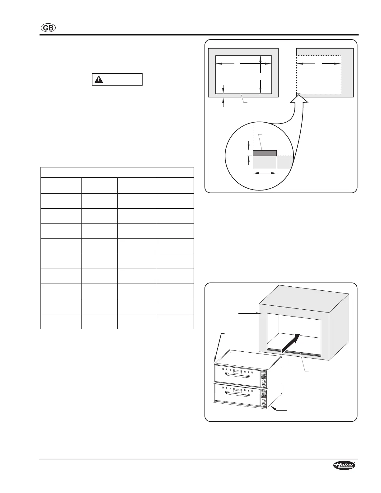
1. Cut the appropriate opening in the cabinet. Refer to the
“Built-In Cutout Dimensions” chart and illustration below
for dimensions.
NOTE:Maintainaminimumclearanceof25mm(1″)between
the cutout opening and the floor.
Built-In Cutout Dimensions
Model
Width
(A)
Depth
(B)
Height
(C)
HDW-1B 720 mm
(28-3/8
610 mm
(24
257 mm
(10-1/8
HDW-2B 720 mm
(28-3/8
610 mm
(24
514 mm
(20-1/4
HDW-3B 720 mm
(28-3/8
610 mm
(24
771 mm
(30-3/8
HDW-1BN 502 mm
(19-3/4
720 mm
(28-3/8
257 mm
(10-1/8
HDW-2BN 502 mm
(19-3/4
720 mm
(28-3/8
514 mm
(20-1/4
HDW-3BN 502 mm
(19-3/4
720 mm
(28-3/8
771 mm
(30-3/8
HDW-1BR 722 mm
(28-7/16
460 mm
(18-1/8
257 mm
(10-1/8
HDW-2BR 722 mm
(28-7/16
460 mm
(18-1/8
529 mm
(20-13/16
HDW-3BR 722 mm
(28-7/16
460 mm
(18-1/8
802 mm
(31-9/16
2. Fasten a locking strip (not supplied) to the lower front
inside lip of the cabinet opening.
3. Make sure a properly grounded electrical supply of the
correct voltage and size is installed inside the cabinet
cutout. See the SPECIFICATIONS section for details.
A
25 mm
(1″)
C
B
Front View
Side View
22 mm
(7/8″)
3 mm
(1/8″)
Locking
Strip
Locking
Strip
Cutout and Locking Strip Dimensions
4. Partially insert the unit into the opening, making sure the
conduit is fed into the opening first.
5. Have a qualified electrician connect the unit wires from the
conduit to the electrical supply inside the cabinet.
6. Before installing the unit into the opening completely, apply
a bead of National Sanitation Foundation-approved sealant
between the heated drawer flange and the cabinet facing.
7. Slide the unit into the opening until the front locking studs
drop behind the locking strip. To verify installation, pull out
the bottom drawer completely and gently pull to ensure the
unit is locked in place.
Heated
Drawer
Flange
Locking
Strip
Cabinet
Facing
Locking Studs
(underneath)
Built-In Installation (HDW-2B Model shown)
 Loading...