7
Place the heat pump outdoors and away from any enclosed technical
space.
Placed under a shelter, the minimum required distances mentioned
below must be respected in order to avoid any risk of air recirculation
and a deficiency in the unit's overall performance.
3. INSTALLATION AND CONNECTION
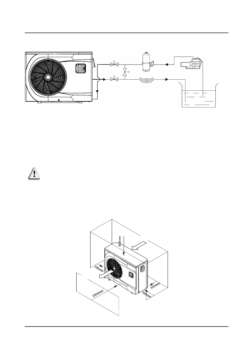
3.1 Functional Diagram
Pool
Water outlet
Chlorinator cell
(or other treatment)
Pump
filtration
FilterWater Inlet
valve
Water outlet
valve
By-pass
valve
Note : The swimming pool heat pump unit is sold without any treatment or
filtration equipment. The components presented in the diagram are
spare parts to be supplied by the installer.
3.2 Heat pump unit
Unit: mm
Air inlet
Air outlet