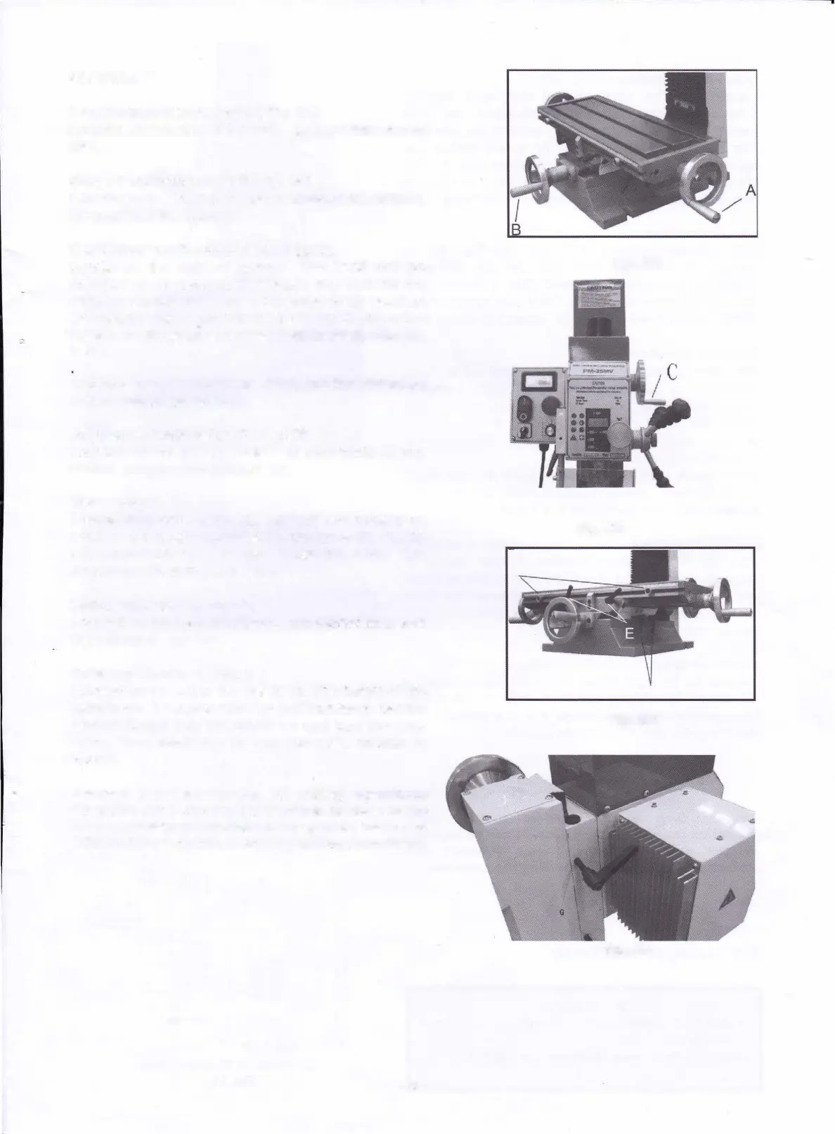
CONTROL
Longitudinal Handwheel {A, Fig. 04)
Located on two
side
of
the
table. Moves
table side
to
side.
Cross
Feed
Handwheel {B, Fig. 04)
Located on the front of the base. Moves table toward,
or
away from the column.
Head Elevating handwheel (C, Fig.05),
Locate
on the right
of column. The head can be
adjusted up or down to suit height requirements for
different
workpieces. Turn it clockwise
to up head on
the
column and counter-clockwise to down.
When the
head is at the desired height, Iock in place with the
locks.
Caution: Have
to
loosen the locks for the slideways
before
above
operation!
Adjustable Table Stops (D, Fig.06)
Located on table front. Adjust to stop table at any
setting along the longitudinal axis.
Table locks
Longitudinal table locks {E, Fig. 06) are located
on
front of the table. Cross-feed table locks (F, Fig.05)
are located on the right
side
under the table. Turn
clockwise to
Iock the slideways.
Mill Head locks (G, Fig.07)
Located
on the right of column. Turn clockwise to Iock
the
mill head.
Quill Lock
Lever
(H, Fig. 07)
Located on
the
left of the mill head. The height of the
spindle can be locked
with
the quill Iock lever. Set the
desired height with
the
quill lever and turn the lever
down. Turn clockwise to Iock
the
quill, reverse to
loosen.
Caution: For best results. Ali
milling
operations
should be done
with the quill/spindle
as
close
to the
head
assembly as possible. Lock spindle, table and
"
mill head in place before starting milling operations!
- 8 -
Fig. 04
Fig. 05
Fig. 06
Fig. 07