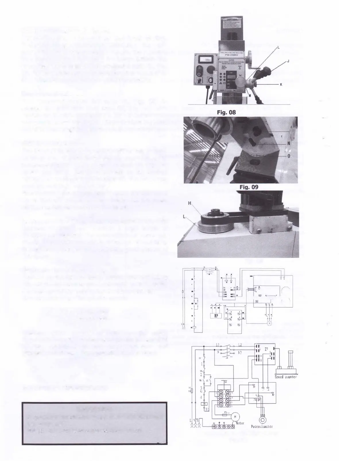
Down feed Handles: (J, Fig. 08):
Located
on the right side
of
the head casting.
Counter-clockwise movement advances the quill
toward the table. Return spring retracts the handles.
The knob (K, Fig.
08)
must be loose before the
operating the handles. The graduated dials (L, Fig.
08) on
the
handle base can be indexed or "zeroed"
to
help make accurate and convenient movements.
Fine
Down
Feed
Turn
counter-clockwise the knob (K, Fig. 08) to
engage the
fine down
feed
knob
(M, Fig. 08) what
located on the front of the head. Turn it according to
you want to move downward,
Clockwise
turn the hand
wheel
to
down feed the spindle, reverse to
retract it.
Mill
Head Rotation
The head is designed
to tilt
90 ° either left or right,
enabling
it to perform
task
such as
angle drilling or
horizontal slotting. Loosen the Iock nuts (N, Fig.
09)
under the head.
Rotate
the head to its desired
position, using the reference guide (0, Fig.09). Once
in place, re-tighten the Iock nuts.
Note: make sure to provide support for the head
so
it doesn't unexpectedly rotate on its own.
AJways maintain control of the head.
Keep in mind that the head must be dialed in when it's
returned to the "zero" position if high levels of
accuracy are required. If you are able to use an angle
vise
to accomplish your milling operation without tilting
the mill head, you will save yourself a good amount of
set-up
time.
High/Low Speed Knob (P, Fig. 10)
Located
on the right of
the mill head. You can select
H/L speed by moving the knob right or left. Note:
Change speed keep machine is
at
low speed!
See the
chart below for
spindle speeds:
L:50-1250
H:100-2500
Caution: Even at low spindle
speeds,
metal
fragments from
the cutting
process can
be
expelled
by the mill/ drill. Always wear eyewear and
protective clothing when operating the machine!
ELECTRICAL CONNECTIONS
WARNING!
A qualified electrician must make all electrical
connections!
Failure to do so may cause serious injury!
Q
Fig.10
D
';
-..____,,
!-='-'-,,=-'--' r-
Schematic for Brush Motor
IN
00T
Schematic for Brushless Motor
Fig.11
\J
Ssnsor