03/03/97
34
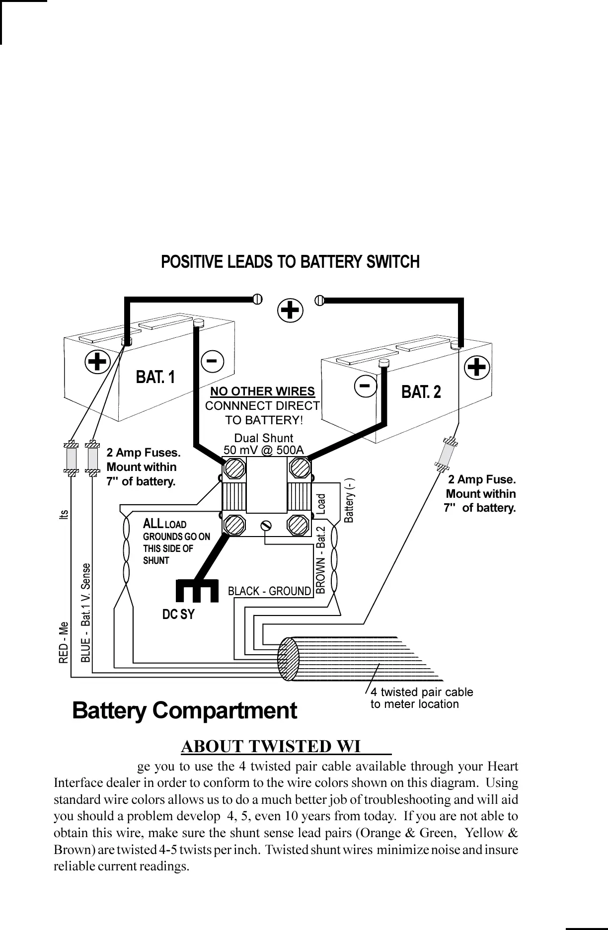
The dual shunt is the current sensor for the Link 20. Its 50mV @ 500A rating means that
when 500 Amps flows through it, 50mV is generated across it. The millivolt signal is
translated into an Amps display in the meter. For example: A 50A load generates 5mV
across the shunt and would be displayed as 050 Amps. Caution: In the diagram below,
the darker wires represent primary wiring and should be able to carry full battery load
current. Size appropriately!
WIRE BY WIRE DETAIL
BATTERY COMPARTMENT
+
-
+
Battery Compartment
2
2
RED - Meter Power 12 OR 24 Volts
BLUE - Bat.1 V. Sense
2 Amp Fuses.
Mount within
7" of battery.
+
-
23456
23456
23456
23456
23456
23456
23456
23456
23456
23456
23456
23456
DC SYSTEM
NEGATIVE
1234567890123456789012345678901212345678901234567
1234567890123456789012345678901212345678901234567
1234567890123456789012345678901212345678901234567
1234567890123456789012345678901212345678901234567
1234567890123456789012345678901212345678901234567
1234567890123456789012345678901212345678901234567
1234567890123456789012345678901212345678901234567
1234567890123456789012345678901212345678901234567
1234567890123456789012345678901212345678901234567
1234567890123456789012345678901212345678901234567
1234567890123456789012345678901212345678901234567
1234567890123456789012345678901212345678901234567
1234567
1234567
1234567
1234567
1234567
1234567
1234567
1234567
1234567
1234567
1234567
1234567
1234567
1234567
ORANGE - Bat.1 Battery (- )
GREEN - Bat.1 Load
VIOLET - Bat.2 V. Sense
YELLOW- Bat.2 Battery (- )
BROWN - Bat.2
Load
BLACK - GROUND
BAT. 2
BAT. 1
POSITIVE LEADS TO BATTERY SWITCH
ALL LOAD
GROUNDS GO ON
THIS SIDE OF
SHUNT
4 twisted pair cable
to meter location
2 Amp Fuse.
Mount within
7" of battery.
Dual Shunt
50 mV @ 500A
ABOUT TWISTED WIRE:
We strongly urge you to use the 4 twisted pair cable available through your Heart
Interface dealer in order to conform to the wire colors shown on this diagram. Using
standard wire colors allows us to do a much better job of troubleshooting and will aid
you should a problem develop 4, 5, even 10 years from today. If you are not able to
obtain this wire, make sure the shunt sense lead pairs (Orange & Green, Yellow &
Brown) are twisted 4-5 twists per inch. Twisted shunt wires minimize noise and insure
reliable current readings.
NO OTHER WIRES
CONNNECT DIRECT
TO BATTERY!