TEST
#4
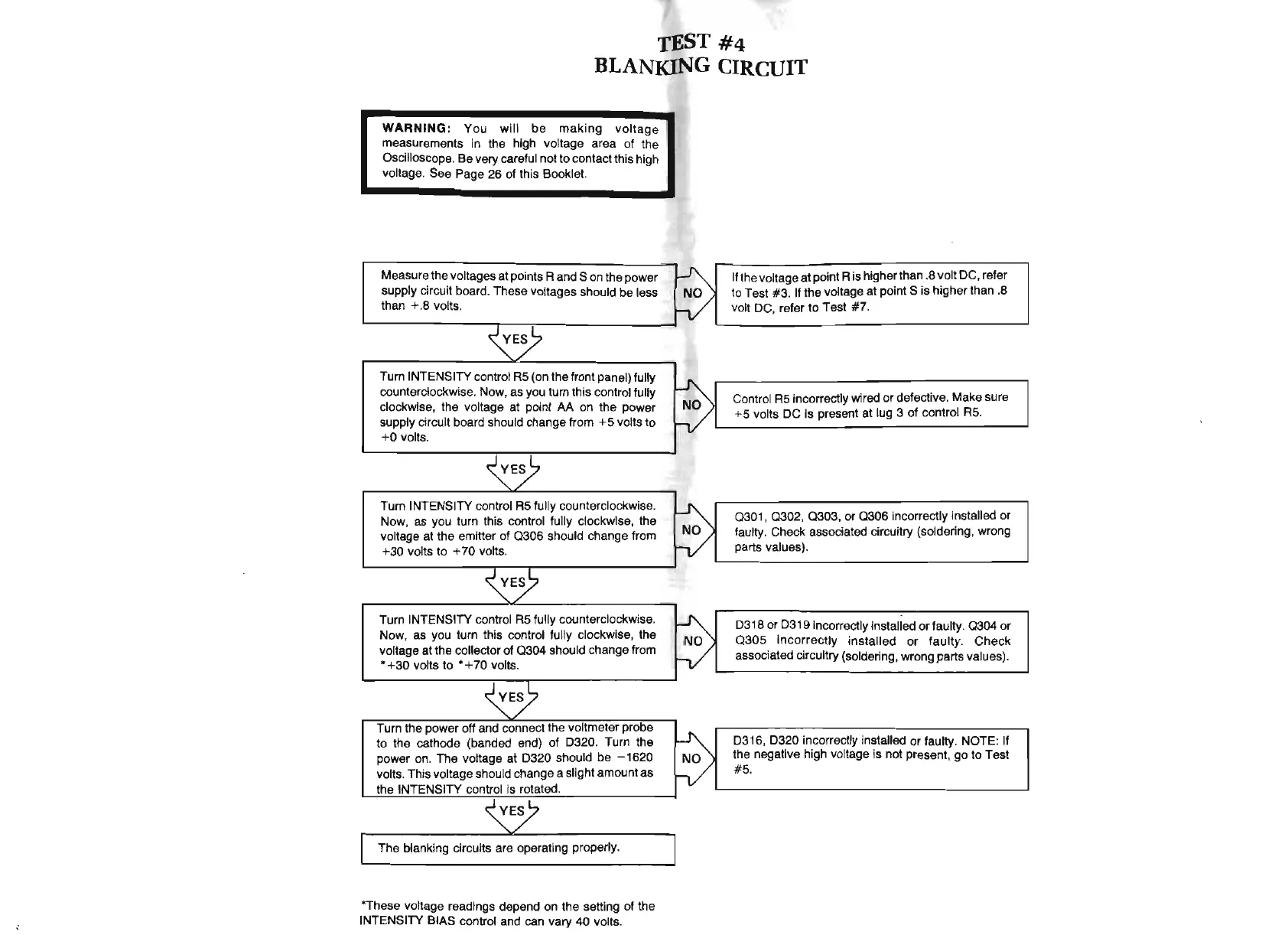
BLANKING CIRCUIT
WARNING:
You
will
be
making
voltag
e
measurements in the high voltage area of the
Oscilloscope. Be very careful not
to
contact this high
voltage. See Page 26 of this Booklet.
Measure the voltages
at
points A and S on the power
supply circuit board. These voltages should be
less
than
+.
8 volts.
~
Turn INTENSITY control
AS
(on the front panel) fully
counterclockwise. Now, as you turn this control fully
clockwise, the voltage at point
AA
on the power
supply circuit board should change from + S volts
to
+0
volts.
~~
Turn INTENSITY control
AS
fully counterclockwise.
Now, as you turn this control
fully clockwise, the
voltage at the emitter of
0306
should change from
+ 30 volts
to
+ 70 volts.
~~
Turn INTENSITY control
AS
fully counterclockwise.
Now, as you turn this control fully clockwise, the
voltage at the collector of
0304
should change from
• +30 volts to • +
70
volts.
~~
Turn the power off and connect the voltmeter probe
to the cathode (banded end) of D320. Turn the
power on. The voltage at D320 should be
-1620
volts. This voltage should change a slight amount as
the INTENSITY control Is rotated.
~
The blanking circuits are operating properly.
*These voltage readings depend on the setting
of
the
INTENSITY BIAS control and can vary 40 volts.
~
If the voltage
at
point A is higher than .8 volt
DC
, refer
to Test #3. If the voltage
at
poi
ntS
is higher than .8
h/
volt DC, refer
to
Test
#7
.
~
h/
Control
AS
incorrectly wired
or
defective. Make sure
+S volts DC is present at lug 3 of con
tr
ol
AS
.
~
030
1,
0302
,
0303,
or
0306
incorrectly installed or
h/
faulty. Check associated circuitry (soldering, wrong
parts values).
~
D318
or
D319 incorrectly installed
or
faulty.
0304
or
030S
incorr
ectly installed
or
faulty
.
Check
h/
associated circuitry (soldering, wrong parts values
).
~
D316, D320 incorrectly installed
or
faulty. NOTE: If
the negative high voltage is not present, go to Test
h/
#S.